
Partition frame type auxiliary chip removal device for circumferential array multi-station numerical control lathe

A circular array and CNC lathe technology, applied in the direction of manufacturing tools, metal processing equipment, metal processing machinery parts, etc., can solve the problems of chip accumulation, machine downtime, etc., to avoid accumulation, improve processing efficiency, and avoid automatic shutdown. Effect

Pending Publication Date: 2022-07-12
DALIAN DEMAISHI PRECISION TECH CO LTD +1
View PDF0 Cites 0 Cited by
  • Summary
  • Abstract
  • Description
  • Claims
  • Application Information

AI Technical Summary

Problems solved by technology

[0004] The object of the present invention is to provide a frame-type auxiliary chip removal device applied to a circular array multi-station CNC machine tool, which is used in conjunction with the existing cutting fluid jet device of the machine tool, so that the cutting fluid jet passes through the blocking reflection of the frame, and finally It flows out of the working area at a height exceeding the tool holder, thereby taking away the chips, and solving the problems of chip accumulation and stopping the machine tool that are common in machining shaft parts on the existing circular array multi-station CNC lathes

Method used


Image

  • Partition frame type auxiliary chip removal device for circumferential array multi-station numerical control lathe
  • Partition frame type auxiliary chip removal device for circumferential array multi-station numerical control lathe
  • Partition frame type auxiliary chip removal device for circumferential array multi-station numerical control lathe

Examples


Embodiment Construction

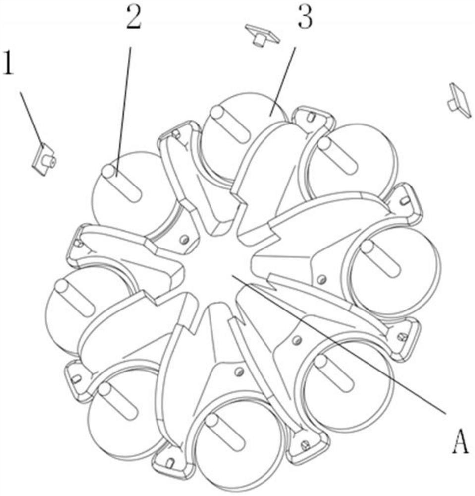
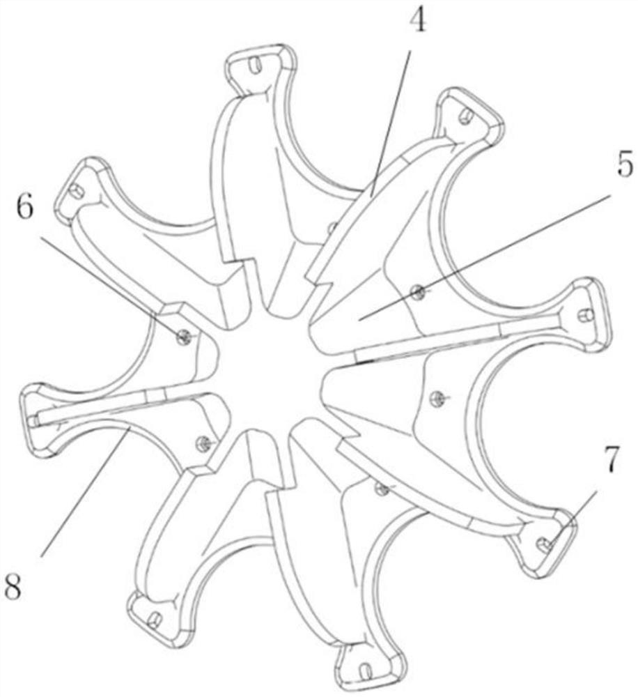
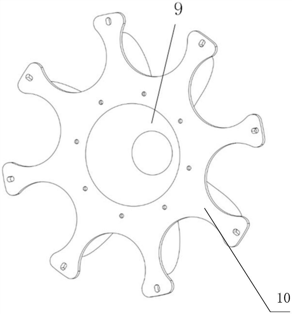
[0022] exist Figure 2 to Figure 3 In the schematic diagram of the present invention shown, the present invention consists of a number of frame structures distributed in an array along the circumference and a base plate 10. The base plate is provided with adjustment holes 7, which are connected and fixed with the machine tool by screws. The edge of the bottom plate has a chamfered design to facilitate the smooth discharge of chips. Several spacer frame mechanisms distributed along the circumference array are connected, and each spacer frame structure is a space fan-shaped area enclosed by the pyramid inclined surface 8 , the spacer plate 4 and the spacer frame bottom plate 5 . The pyramid inclined surface 8 is provided with a circular array of stepped screw through holes 6, which are connected and fixed with the machine tool by screws. There is a hollow 9 design inside the pyramid to reduce the mass of the device. The edges and corners of the separator are rounded to facilit...


PUM


Abstract

A bulkhead type auxiliary chip removal device for a circumferential array multi-station numerical control lathe is composed of a plurality of bulkhead mechanisms distributed in a circumferential array mode and a bottom plate, the bulkhead mechanisms distributed in the circumferential array mode are connected, and each bulkhead structure is a spatial fan-shaped area defined by a pyramid slope, a partition plate and a bulkhead bottom plate. The number of the bulkhead structures corresponds to the number of circumferential stations of a machine tool. When the device is mounted, the radial cutting fluid jet flow of each station firstly impacts the partition plate and forms an oblique angle of 30-50 degrees with the partition plate. The device is used in cooperation with an existing cutting fluid jet flow device of a machine tool, so that cutting fluid jet flow is shielded and reflected by the partition frame and finally flows out of a working area at the height exceeding a tool rest, cuttings are taken away, and the common problems that when an existing circumferential array multi-station numerical control lathe is used for machining shaft parts, cuttings are accumulated, and the machine tool is stopped are solved. The shutdown time of the circumferential array multi-station numerical control lathe can be greatly shortened, and the machining efficiency is improved.

Description

technical field [0001] The invention relates to the technical field of machining, in particular to a frame-type auxiliary chip removal device for a circular array multi-station numerically controlled lathe. Background technique [0002] The circular array multi-station CNC lathe can perform multiple processes such as drilling, reaming, and external turning at the same time. With the automatic loading and unloading device, it can realize automatic continuous processing of complex shaft parts with multiple processes. During the machining process of the circular array multi-station CNC lathe, each station will continuously generate chips due to the simultaneous multi-station operation. The chips of each station are affected by the cutting fluid sprayed from the respective tool holders, and converge near the center of the machine tool table. Since there is no shielding or drainage structure for the cutting fluid between the various stations of the existing circular array multi-...

Claims


Application Information

Patent Timeline
IPC IPC(8): B23Q11/00
CPCB23Q11/0042Y02P70/10
Inventor 骆波阳刘国龙苏英峰魏兆成郭明龙姜皓晨于连荣
Owner DALIAN DEMAISHI PRECISION TECH CO LTD
Learn More