
Directional routing debugging mechanism based on request tag expression

An expression and mechanism technology, applied in the field of optoelectronic information, which can solve the problems of R&D engineers' realization difficulties and the inability to rebuild the microservice environment.

Pending Publication Date: 2022-07-08
深圳市铱云云计算有限公司
View PDF0 Cites 0 Cited by
  • Summary
  • Abstract
  • Description
  • Claims
  • Application Information

AI Technical Summary

Problems solved by technology

In addition, a unified and centralized service management mechanism should be avoided as much as possible. For a specific service, an appropriate language and tool should be selected according to the context to build it. The existing single application refers to a war package Contains all the functions of the project, such as the common taxi application. Although there is a logical modular architecture, the application is packaged and deployed as a single unit. For example, many Java applications we know are packaged as WAR Files are deployed on application servers such as Tomcat or Jetty, and other Java applications are packaged into executable JAR packages. In the era of monolithic applications, R&D engineers first need to go through the local debugging function when developing and debugging new functions. Complete independent verification and then submit the code, then build the code, and finally deploy it on the development environment or test. However, in the era of microservices, if this follows the original logic, the R&D engineer locally debugs the code, and the independent test is completed and submitted for deployment. This process It is difficult for R&D engineers to implement local debugging codes. R&D engineers cannot rebuild a whole set of more than dozens of microservice environments. Therefore, based on the above problems, the present invention will provide a

Method used


Image

  • Directional routing debugging mechanism based on request tag expression
  • Directional routing debugging mechanism based on request tag expression
  • Directional routing debugging mechanism based on request tag expression

Examples


Embodiment Construction

[0025] Based on the embodiments of the present invention, all other embodiments obtained by those of ordinary skill in the art without creative efforts shall fall within the protection scope of the present invention.

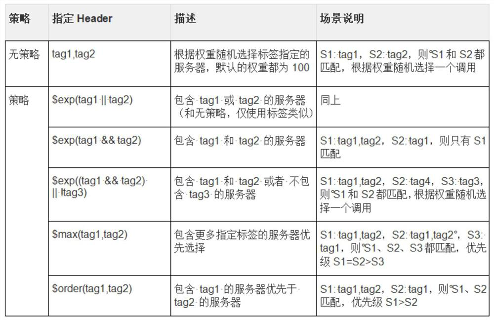
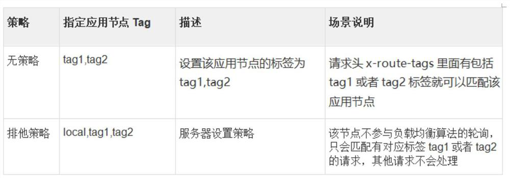
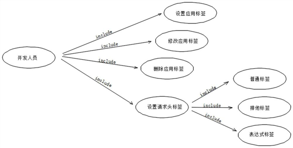
[0026] The present invention provides a technical solution: a directional routing debugging mechanism based on a request label expression, the debugging mechanism provided by the present invention is a micro-service architecture constructed by the system using the Java open source framework SpringCloud, and the direct mutual invocation of micro-services in the SpringCloud framework is achieved through HTTP protocol calls, each microservice uses the Ribbon component to do client local load balancing, and implements load balancing between microservices. The core principle is to add a special request header to the HTTP call. This request header is in each All sub-links are transparently transmitted to the next sub-link. By transforming the Ribbon component, Ribbon c...


PUM


Abstract

The invention discloses a directional routing debugging mechanism based on a request tag expression, the debugging mechanism provided by the invention is a micro-service architecture constructed by adopting a Java open source framework SpringCloud, direct mutual calling of micro-services in the SpringCloud framework is realized through HTTP (Hyper Text Transport Protocol), and each micro-service performs client local load balancing by adopting a Ribbon component. The routing debugging mechanism is directed based on the request tag expression. According to the directional routing debugging mechanism based on the request label expression, developers can set corresponding labels for the applications according to own requirements when the applications are started, weights corresponding to label values of the applications can be modified on a unified application node interface, and the developers can conveniently debug the functions when the developers debug the functions. A corresponding label can be added to an Http request header, and then the request finally accesses a specified application node according to the rule of the label regardless of the length of a midway link.

Description

technical field [0001] The invention relates to the technical field of optoelectronic information, in particular to a directional routing debugging mechanism based on a request label expression; Background technique [0002] Existing microservices refer to a software development technique - a variant of the service-oriented architecture (SOA) architectural style, which advocates dividing a single application into a set of small services that coordinate and cooperate with each other , providing the ultimate value to the user. Each service runs in its independent process, and the services communicate with each other using a lightweight communication mechanism (usually HTTP-based RESTful API). Each service is built around a specific business and can be independently deployed to production environments, production-like environments, etc. In addition, a unified and centralized service management mechanism should be avoided as much as possible. For a specific service, appropriat...

Claims


Application Information

Patent Timeline
IPC IPC(8): H04L45/50H04L67/02
CPCH04L45/50H04L45/507H04L67/02Y02D30/50
Inventor 罗国财
Owner 深圳市铱云云计算有限公司
Learn More