
Ladder program display device

A technology of trapezoidal program and display device, which is applied in the direction of program control, instrument, test/monitoring control system, etc. It can solve the problems of unsure self-holding circuit, etc., and achieve the effect of easy discovery, easy failure cause and high operation efficiency

Inactive Publication Date: 2017-08-01
FANUC LTD
View PDF1 Cites 1 Cited by
  • Summary
  • Abstract
  • Description
  • Claims
  • Application Information

AI Technical Summary

Problems solved by technology

[0012] In the technology disclosed in the above-mentioned Japanese Patent Application Laid-Open No. 07-160312, the above-mentioned process 2 can be simplified, but the self-holding circuit of the above-mentioned process 1 cannot be determined.

Method used


Image

  • Ladder program display device
  • Ladder program display device
  • Ladder program display device

Examples


Embodiment Construction

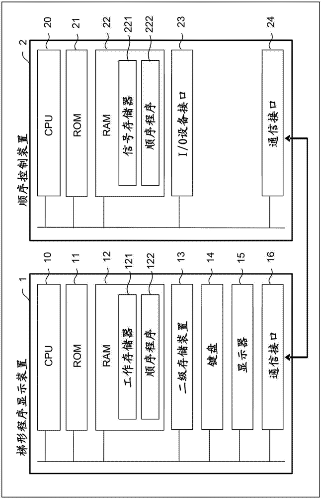
[0029] figure 1 It is a schematic configuration diagram of a ladder program display device according to an embodiment of the present invention.

[0030] The ladder program display device 1 of the present embodiment has a CPU 10 , a ROM 11 , a RAM 12 , a secondary storage device 13 , a keyboard 14 , a display 15 , and a communication interface 16 .

[0031] The CPU 10 included in the ladder program display device 1 is a processor that controls the ladder program display device 1 as a whole, reads the system program stored in the ROM 11 via the bus, and controls the ladder program display device 1 according to the system program. The system program also includes a program for extracting the self-holding circuit from the sequence program and a program for setting the address of the signal used in the self-holding circuit as the tracking target. By executing this program, the following function and Image 6 Each processing described in the flow.

[0032] The RAM 12 is provided...


PUM


Abstract

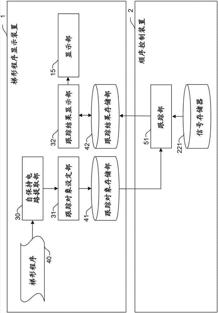
A ladder program display device displays an operation status of a ladder program executed by a sequence controller, in which a self-holding circuit is extracted from the ladder program, a signal address used in the extracted self-holding circuit is set as a signal address to be traced, and the display of a result of tracing the signal address by the sequence controller is outputted.

Description

technical field [0001] The invention relates to a ladder program display device, in particular to a ladder program display device with an automatic tracking function of a ladder program self-holding circuit. Background technique [0002] When a defect, which is a phenomenon unexpected to the user, occurs during the operation of the programmable controller, it is generally known that a signal causing the defect and a change in a related signal are confirmed using a trace function to determine the cause. [0003] The so-called trace function is a function of recording the state of each signal in time series and displaying the recording result. As a method of using the tracking function, there is a method, such as a method disclosed in Japanese Patent Application Laid-Open No. 07-160312, of automatically searching for affected contacts for a specified coil and setting the affected contacts as tracking targets. [0004] In the ladder program, in order to maintain the signal sta...

Claims


Application Information

Patent Timeline
Patent Type & Authority Applications(China)
IPC IPC(8): G05B23/02
CPCG05B23/0262G05B2219/24065G06F11/348G06F11/0736G06F11/0751G06F11/079G06F11/302G06F11/3055G06F11/324G06F11/3471G06F2201/865
Inventor 佐藤亘
Owner FANUC LTD
Learn More