Rotor assembly, permanent magnet motor and compressor

A component and rotor technology, applied in the direction of electric components, magnetic circuit rotating parts, magnetic circuits, etc., can solve the problem of affecting the performance and reliability of motors and compressors, the weakening of the anti-demagnetization ability of rotor permanent magnets, and affecting the service life of products, etc. question

Pending Publication Date: 2022-07-05
ANHUI MEIZHI PRECISION MFG
View PDF0 Cites 0 Cited by
  • Summary
  • Abstract
  • Description
  • Claims
  • Application Information

AI Technical Summary

Problems solved by technology

[0002] At this stage, air-conditioning compressors at home and abroad basically use variable frequency motors, and variable frequency motors generally use permanent magnet motors. The excitation method of permanent magnet motor rotors is excited by permanent magnets. Due to the characteristics of high power density of permanent magnet motors and the need for cost reduction, the rotor The ability of permanent magnets to resist demagnetization is weakened
When the permanent magnet is irreversibly demagnetized, it will affect the operating performance and reliability of the motor and compressor, and seriously affect the service life of the product

Method used


Image

  • Rotor assembly, permanent magnet motor and compressor
  • Rotor assembly, permanent magnet motor and compressor
  • Rotor assembly, permanent magnet motor and compressor

Examples


Embodiment 1

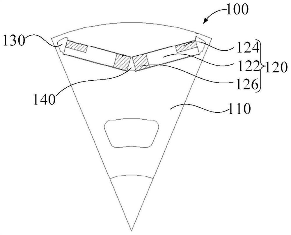
[0060] like figure 1 , figure 2 and image 3 As shown, the embodiment of the first aspect of the present invention provides a rotor assembly 100. The rotor assembly 100 includes:

[0061] The rotor iron core 110 includes a through hole; the permanent magnet 120 is arranged in the through hole, and the permanent magnet 120 is cut through a plane perpendicular to the axis of the rotor iron core 110 to obtain a first cross section. On the first cross section, the permanent magnet 120 is extension direction ( image 3 The included angle between the B direction is the extension direction) and the radial direction of the rotor core 110 is greater than 0° and less than 90°. The permanent magnet 120 includes: a non-diffusion part 122, and in the extension direction, the non-diffusion part 122 includes: The first end and the second end, the first end is adjacent to the peripheral side surface of the rotor core 110, and the second end is adjacent to the axis of the rotor core 110; t...

Embodiment 2

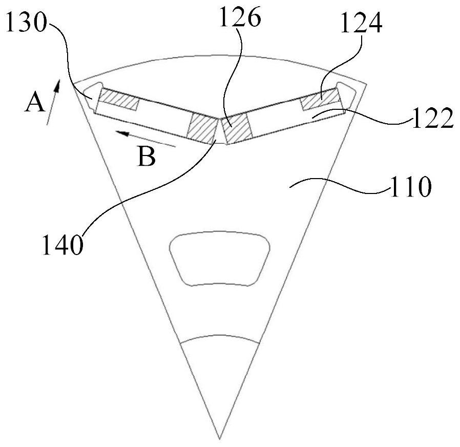
[0070] like figure 1 , figure 2 and image 3 As shown, in the embodiment of the second aspect of the present invention, in the radial direction of the rotor iron core 110, the distance between the first magnetic isolation bridge 130 and the circumferential side surface of the rotor iron core 110 is W1; length is L1 where W1 1.3 ×L1=K1, 0.04≤K1≤0.57.

[0071] In this embodiment, the dimensional relationship between the first magnetic isolation bridge 130 and the first diffusion part 124 is defined. Specifically, the distance between the first magnetic isolation bridge 130 and the peripheral side surface of the rotor iron core 110 is W1, that is, in the radial direction, the minimum distance between the first magnetic isolation bridge 130 and the peripheral side surface of the rotor iron core 110 is W1. On the first cross section, the length of the first diffusion part 124 in the extending direction of the permanent magnet 120 is L1. On this basis, W1 and L1 satisfy the f...

Embodiment 3

[0075] like figure 1 , figure 2 and image 3 As shown, in the embodiment of the third aspect of the present invention, two permanent magnets 120 are a group, and the rotor assembly 100 includes multiple groups of permanent magnets 120; on the first cross-section, the two permanent magnets 120 of the same group are distributed in a V-shape.

[0076] In this embodiment, the layout of the permanent magnets 120 on the rotor assembly 100 is defined. Specifically, each rotor assembly 100 is provided with a plurality of groups of permanent magnets 120 , and the plurality of groups of permanent magnets 120 are arranged around the axis of the rotor core 110 . Each group of permanent magnets 120 includes two permanent magnets 120, and the two permanent magnets 120 are symmetrically arranged on both sides of the first plane. The axis of the rotor iron core 110 and the diameter of the rotor iron core 110 are both in the first plane. Specifically, the rotor iron core 110 and the perman...


PUM


Abstract

The invention provides a rotor assembly, a permanent magnet motor and a compressor, and the rotor assembly comprises a rotor iron core which comprises a through hole; the permanent magnet is arranged in the through hole, the permanent magnet is cut out through a surface perpendicular to the axis of the rotor iron core to obtain a first section, the included angle between the extension direction of the permanent magnet and the radial direction of the rotor iron core is larger than 0 degree and smaller than 90 degrees on the first section, the permanent magnet comprises a non-diffusion part, and the non-diffusion part comprises a first end and a second end in the extension direction, the first end is close to the circumferential side of the rotor core, and the second end is close to the axis of the rotor core; the first diffusion part is connected with the first end of the non-diffusion part; the first magnetic isolation bridge is connected with the first diffusion part and is positioned between the first diffusion part and the circumferential side surface of the rotor iron core; wherein the mass ratio of the heavy metal elements in the first diffusion part is greater than the mass ratio of the heavy metal elements in the non-diffusion part. According to the invention, the technical problems that the anti-demagnetization capability of the permanent magnet motor is weak and irreversible demagnetization is easy to occur are solved.

Description

technical field [0001] The present invention relates to the technical field of compressors, and in particular, to a rotor assembly, a permanent magnet motor and a compressor. Background technique [0002] At present, air-conditioning compressors at home and abroad basically use variable frequency motors, and variable frequency motors generally use permanent magnet motors. The excitation method of permanent magnet motor rotors is excitation by permanent magnets. Due to the characteristics of high power density of permanent magnet motors and the need for cost reduction, the rotor The resistance to demagnetization of permanent magnets is weakened. When the permanent magnet is irreversibly demagnetized, it will affect the operation performance and reliability of the motor and compressor, and seriously affect the service life of the product. [0003] Therefore, how to design a rotor assembly that can effectively solve the above technical defects has become an urgent technical pr...

Claims


Application Information

Patent Timeline
IPC IPC(8): H02K1/276H02K1/2753H02K1/28
CPCH02K1/276H02K1/2753H02K1/28H02K2213/03
Inventor 李宏涛于岚邱小华
Owner ANHUI MEIZHI PRECISION MFG
Why Eureka
Try Eureka