
Online visual detection system in LNG (Liquefied Natural Gas) tank and implementation method

A detection system and detection probe technology, applied in the field of LNG storage tanks, can solve problems such as uneven shrinkage of inner wall panels and equipment, lack of online integrity detection technology for LNG storage tanks, and storage tank defects.

Pending Publication Date: 2022-07-05
CNOOC GAS & POWER GRP
View PDF0 Cites 0 Cited by
  • Summary
  • Abstract
  • Description
  • Claims
  • Application Information

AI Technical Summary

Problems solved by technology

The particularity of the LNG medium causes the inner wall and internal equipment to shrink and deform after the LNG storage tank built at room temperature is filled with LNG liquid. Potential welding quality problems in the construction stage or frequent periodic stress changes may cause defects in the storage tank.
[0003] After technical literature research, the current online integrity detection technology for LNG storage tanks is relatively scarce. The existing patent applications are mainly that all functional components of the detection device are concentrated in a closed cavity, and the detection device is from the tank top through the hard rod below to the tank. Integrity detection such as shrinkage unevenness of inner wall panels and equipment, local deformation of wall panels and equipment, and actual inner tank volume after liquid filling of LNG storage tanks, or through wireless suspension mobile detection methods
As for the on-site construction method of the visual detection device inside the LNG tank under the operating state, it is still blank

Method used


Image

  • Online visual detection system in LNG (Liquefied Natural Gas) tank and implementation method
  • Online visual detection system in LNG (Liquefied Natural Gas) tank and implementation method
  • Online visual detection system in LNG (Liquefied Natural Gas) tank and implementation method

Examples


Embodiment Construction

[0026] In order to make the purpose, technical solutions and advantages of the embodiments of the present invention clearer, the technical solutions of the embodiments of the present invention will be clearly and completely described below with reference to the accompanying drawings of the embodiments of the present invention. Obviously, the described embodiments are some, but not all, embodiments of the present invention. Based on the described embodiments of the present invention, all other embodiments obtained by those of ordinary skill in the art fall within the protection scope of the present invention.

[0027] It should be noted that the terminology used herein is for the purpose of describing specific embodiments only, and is not intended to limit the exemplary embodiments according to the present application. As used herein, unless the context clearly dictates otherwise, the singular is intended to include the plural as well, furthermore, it is to be understood that w...


PUM


Abstract

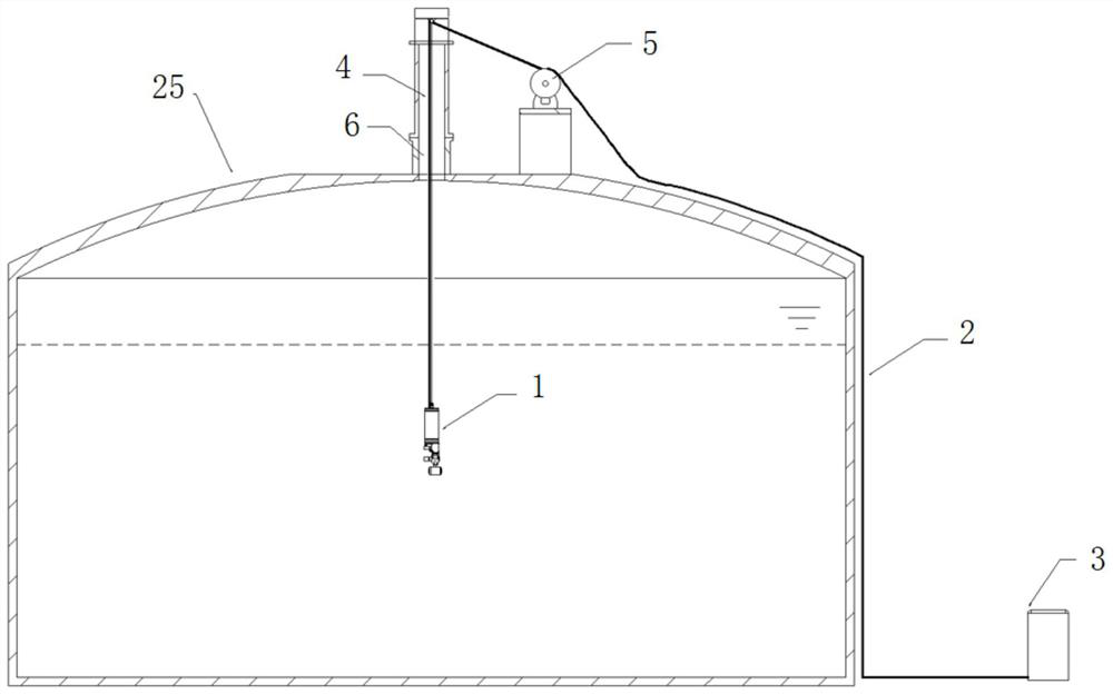
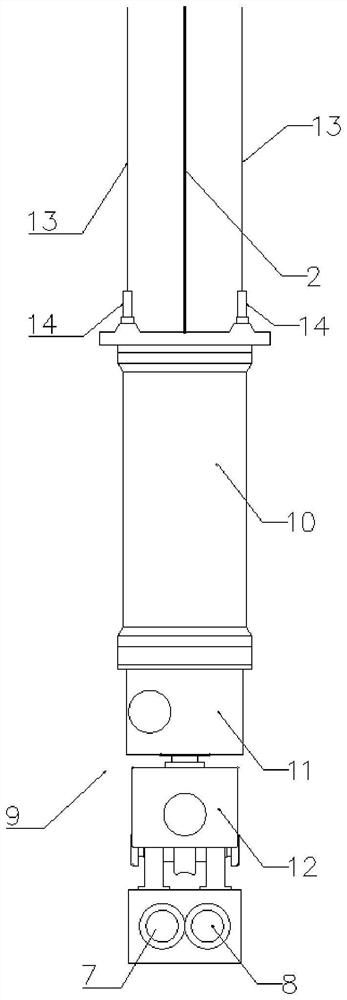
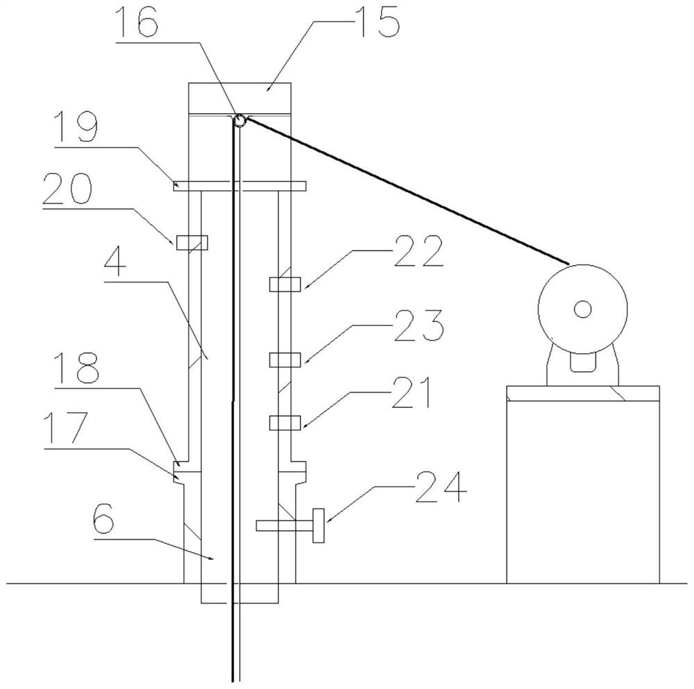
The invention relates to an online visual detection system in an LNG (Liquefied Natural Gas) tank and an implementation method. The online visual detection system comprises a low-temperature detection probe, a control and power supply cable and a ground control system, the low-temperature detection probe is arranged in the LNG storage tank and transmits detected data to the ground control system outside the LNG storage tank through the control and power supply cable; the system further comprises a sleeve, an electric winch and a tank top preformed hole. The tank top preformed hole is formed in the top of the LNG storage tank, the sleeve is arranged on the upper portion of the tank top preformed hole, and the electric winch is arranged on one side of the top of the LNG storage tank. One end of the control and power supply cable is connected with the low-temperature detection probe, and the other end of the control and power supply cable penetrates out of the LNG storage tank after sequentially passing through the tank top preformed hole and the sleeve, and is connected with the ground control system through the electric winch. According to the invention, visual detection of the interior of the LNG storage tank in an operation state is realized.

Description

technical field [0001] The invention relates to the technical field of LNG storage tanks, in particular to an online visual detection system and an implementation method in an LNG tank. Background technique [0002] The particularity and storage characteristics of the LNG medium make the LNG storage tank remain in service until the end of its design life once it is put into use. The particularity of the LNG medium leads to the shrinkage and deformation of the inner wall and internal equipment of the LNG storage tank built at room temperature after filling with LNG liquid. The possible welding quality problems or frequent periodic stress changes during the construction stage may cause defects in the storage tank. . [0003] After technical literature research, the current online integrity detection technology of LNG storage tanks is relatively lacking. The existing patent applications are mainly that all functional components of the detection device are concentrated in a clo...

Claims


Application Information

Patent Timeline
Patent Type & Authority Applications(China)
IPC IPC(8): F17C13/02G01D21/02
CPCF17C13/02F17C13/025F17C13/026G01D21/02F17C2250/043F17C2250/0439F17C2250/0491
Inventor 杨玉霞付子航黄洁馨陈锐莹吴健宏杨宏伟韩银杉冯亮刘方王亚群
Owner CNOOC GAS & POWER GRP
Learn More