Gas suction device for vacuum cavity

A suction device, vacuum chamber technology, applied in pump devices, liquid variable capacity machinery, pump components, etc., can solve the problems of high output power requirements, unstable vacuum value, reduced service life, etc., and achieve extended service life. , Improve sealing and prevent impact

Pending Publication Date: 2022-07-01
SUZHOU TERUITE ROBOT CO LTD
View PDF0 Cites 0 Cited by
  • Summary
  • Abstract
  • Description
  • Claims
  • Application Information

AI Technical Summary

Problems solved by technology

In the prior art, when the chamber is evacuated, due to the large pressure difference between the air pressure in the chamber and the outside air pressure, and the time delay when the valve is closed, the vacuum value in the chamber will be unstable.
Moreover, the adsorption force generated by the large internal and external pressure difference has a high output power requirement for the valve closing mechanism, and the valve opening and closing mechanism with large kinetic energy will cause impact on the cavity and reduce its service life.

Method used


Image

  • Gas suction device for vacuum cavity
  • Gas suction device for vacuum cavity
  • Gas suction device for vacuum cavity

Examples


Embodiment 1

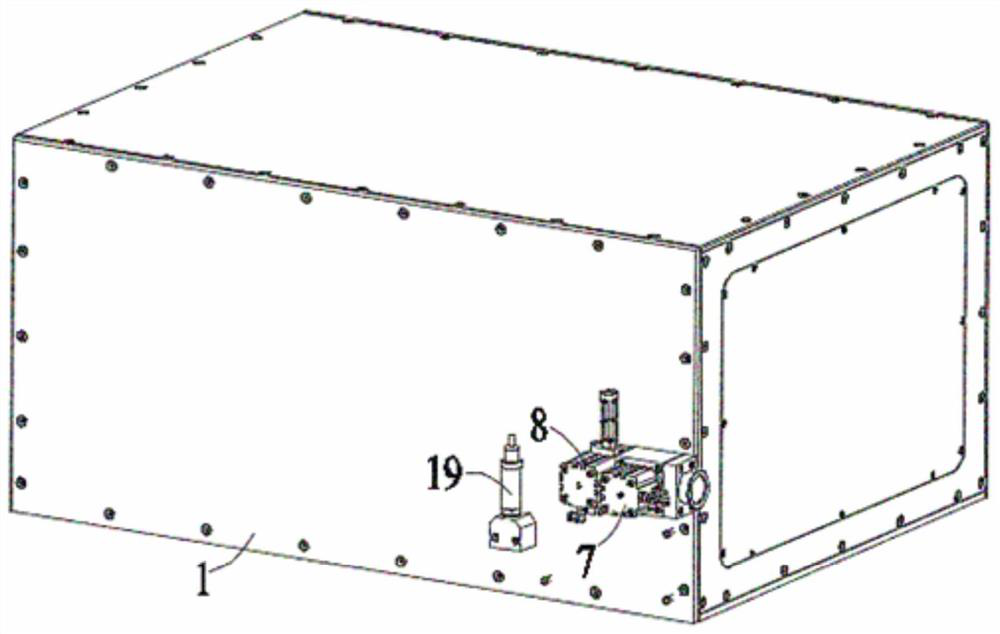
[0025] Embodiment 1: A gas suction device for a vacuum chamber is installed on a vacuum chamber body 1, and the outer surface of one side of the vacuum chamber body 1 is provided with a suction port 2 and an air inlet 3 , the suction port 2 and the air inlet 3 have a radially inwardly protruding flange portion 4 on the inner wall of the inner end of the vacuum chamber body 1, and a first flange 5 is embedded in the suction port 2 Inside, a second flange 6 is embedded in the air inlet 3, and the end faces of each end of the first flange 5 and the second flange 6 are in contact with the end face of the corresponding flange portion 4. The other ends of the first flange 5 and the second flange 6 are connected with the correspondingly arranged piston rods of the first cylinder 7 and the second cylinder 8;

[0026] A connecting seat 9 is installed on the air extraction port 2 , one end face of the connecting seat 9 is connected with the vacuum chamber body 1 , the first cylinder 7 i...

Embodiment 2

[0034] Embodiment 2: A gas suction device for a vacuum chamber is installed on a vacuum chamber body 1, and an outer surface of one side of the vacuum chamber body 1 is provided with an air suction port 2 and an air inlet port 3 , the suction port 2 and the air inlet 3 have a radially inwardly protruding flange portion 4 on the inner wall of the inner end of the vacuum chamber body 1, and a first flange 5 is embedded in the suction port 2 Inside, a second flange 6 is embedded in the air inlet 3, and the end faces of each end of the first flange 5 and the second flange 6 are in contact with the end face of the corresponding flange portion 4. The other ends of the first flange 5 and the second flange 6 are connected with the correspondingly arranged piston rods of the first cylinder 7 and the second cylinder 8;

[0035]A connecting seat 9 is installed on the air suction port 2, one end face of the connecting seat 9 is connected with the vacuum chamber body 1, the first cylinder ...


PUM


Abstract

The invention discloses a gas suction device for a vacuum cavity, which is mounted on a vacuum bin body, an extraction opening and a gas inlet are arranged on the outer surface of one side of the vacuum bin body, a first flange plate is embedded into the extraction opening, a second flange plate is embedded into the gas inlet, and the first flange plate and the second flange plate are connected through a connecting rod. The end faces of one ends of the first flange plate and the second flange plate are in surface contact with the end faces of the corresponding flange parts, the other ends of the first flange plate and the second flange plate are connected with piston rods of a first air cylinder and a second air cylinder which are correspondingly arranged, and the piston rod of the first air cylinder is connected with the first flange plate through a first mandrel. The first mandrel is sleeved with an elastic piece, a cushion block is arranged between the first air cylinder and the connecting base, and the other end of the elastic piece is connected with the cushion block in an extruding mode. In the opening process of the first flange plate, collision caused by too fast contraction can be prevented, and the service life of the mechanism is prolonged.

Description

technical field [0001] The invention relates to the technical field of vacuum cavity sealing, and in particular, to a gas suction device for a vacuum cavity. Background technique [0002] The vacuum chamber is mainly used in the field of product dispensing and packaging. Using the force of negative pressure, the air in the vacuum box is first pumped away during the pouring process, and then the product is poured, which can quickly penetrate the glue into the product and inject shock. And the bubbles generated by the contact between the glue and the product can also be quickly removed under the action of negative pressure, thus ensuring the high performance of the product. In the prior art, when the cavity is evacuated, due to the large pressure difference between the air pressure in the cavity and the outside air pressure, and the time delay when the valve is closed, the vacuum value in the cavity is unstable. In addition, the adsorption force generated by the large interna...

Claims


Application Information

Patent Timeline
Patent Type & Authority Applications(China)
IPC IPC(8): F04B39/12F04B39/00F04B41/02
CPCF04B39/123F04B39/00F04B41/02
Inventor 陈晓峰杨春雨
Owner SUZHOU TERUITE ROBOT CO LTD
Why Eureka
Try Eureka