
Gantry crane rail clamping device

A rail clamp and gantry crane technology, applied in the field of rail transit, can solve the problems of the gantry crane being blown down by the wind, the gap between the side of the rail clamp and the track, and the inclination of the gantry crane, etc., and achieve the effect of ensuring stability.

Pending Publication Date: 2022-06-28
葛丹丹
View PDF0 Cites 0 Cited by
  • Summary
  • Abstract
  • Description
  • Claims
  • Application Information

AI Technical Summary

Problems solved by technology

[0003] 1. When using the rail clamp, it needs to be clamped on the track. Therefore, when the rail clamp is not working, the clamping device does not clamp the track. At this time, the gap between the side of the rail clamp and the track is large. Under strong wind blowing, it is easy to cause the gantry crane to tilt, etc. At the same time, the electric rail clamp uses electric power to achieve the hydraulic effect to push the clamp to clamp the rail. Once the power is cut off during the work, it is easy The hydraulic cylinder loses its power source so that the hydraulic effect cannot be achieved. If the rail clamp is in use at this time, it will cause the danger of the gantry crane being blown down by the wind. It cannot realize self-locking protection, and at the same time, the rail clamp is suddenly powered off. Rapid changes in hydraulic pressure under certain conditions will also cause damage to the interior of the body;
[0004] 2. When the rail clamp works, the clamping device on both sides is used to clamp the track, so it will inevitably cause severe friction between the clamping device and the track under long-term use, and the friction on both sides may also be affected by different external factors. Factors are different, so under the same hydraulic pressure, the force of the clamping device when clamping the track is inconsistent, so that the time for both sides of the track to reach the same clamping force is different, resulting in the tilt of the rail clamp and other situations that affect the stability of the gantry crane.

Method used


Image

  • Gantry crane rail clamping device
  • Gantry crane rail clamping device
  • Gantry crane rail clamping device

Examples


Embodiment Construction

[0024] The technical solutions in the embodiments of the present invention will be clearly and completely described below with reference to the accompanying drawings in the embodiments of the present invention. Obviously, the described embodiments are only a part of the embodiments of the present invention, but not all of the embodiments. Based on the embodiments of the present invention, all other embodiments obtained by those of ordinary skill in the art without creative efforts shall fall within the protection scope of the present invention.

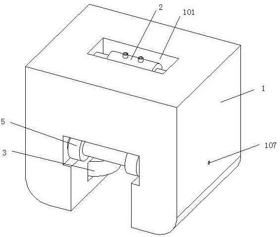
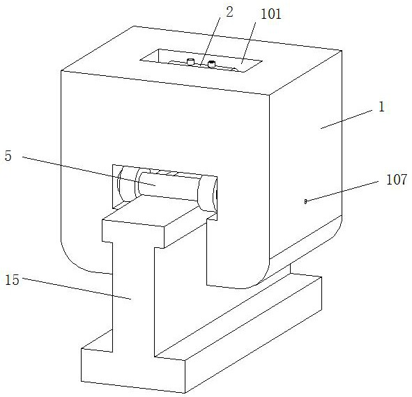
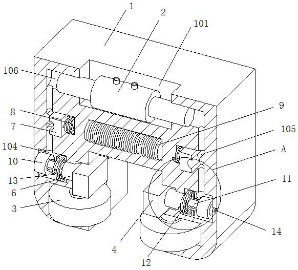
[0025] Please see attached figure 1 -Attached Image 6 , a gantry crane rail clamp, comprising a body 1, the top of the body 1 is provided with a top groove 101, a hydraulic cylinder 2 is installed inside the top groove 101, the body 1 is in the shape of an inverted concave and a wheel groove 102 is symmetrically opened on the inner side of the bottom, There are rollers 3 movably installed inside the wheel groove 102. The rollers 3 a...


PUM


Abstract

The invention relates to the technical field of rail traffic, and discloses a gantry crane rail clamping device which is characterized in that a clamping block is movably sleeved with a sliding groove, a hydraulic control cavity communicated with a machine body is formed in the position, between a hydraulic cavity and a hydraulic hole, in the machine body, and a sliding block is movably sleeved with the hydraulic control cavity; a sleeve is fixedly installed at the position, close to the air guide hole, of the inner side of the hydraulic cavity, a one-way valve is fixedly installed in the air guide hole, an adjusting column is movably connected into the sleeve in a sleeved mode, a limiting groove is formed in the adjusting column in a cross shape, and a sliding rod is movably connected into the limiting groove in a sleeved mode. The stability and power-off self-locking of the rail clamping device are achieved through the arrangement of bottom rolling wheels, a sliding block and an electromagnet, meanwhile, a sleeve is arranged in a hydraulic cavity and connected with an adjusting column in a sleeving mode, and a limiting groove is formed in the adjusting column and connected with a sliding rod in a sleeving mode, so that it can be guaranteed that the rail clamping device still keeps stable due to friction influence in the working process.

Description

technical field [0001] The invention relates to the technical field of rail transit, in particular to a gantry crane rail clamp. Background technique [0002] Large-scale gantry cranes and other machinery are moved through guide rails. When in use, they need to be stopped and fixed on the track to work. Since the equipment is too large, it is easily disturbed by strong winds or even blown down. Therefore, it is necessary to use The rail clamp clamps and fixes the gantry crane and the guide rail together to ensure the overall stability. The existing rail clamps are generally driven by electric or hydraulic power, which can quickly clamp in a short time. However, these rail clamps are still There are certain problems: [0003] 1. When using the rail clamp, it needs to be clamped on the track. Therefore, when the rail clamp is not working, the clamping device does not clamp the rail. At this time, the gap between the side of the rail clamp and the rail is large. Under the str...

Claims


Application Information

Patent Timeline
IPC IPC(8): B66C9/18
CPCB66C9/18
Inventor 葛丹丹
Owner 葛丹丹
Learn More