Safe and stable rail protection device

A protective device, a safe and stable technology, applied in road safety devices, tracks, roads, etc., can solve problems such as large safety hazards, looseness or displacement, and achieve extended service life, long service life, and avoid force deformation and displacement. Effect

Active Publication Date: 2022-06-24
北京航天长城卫星导航科技有限公司
View PDF17 Cites 2 Cited by
  • Summary
  • Abstract
  • Description
  • Claims
  • Application Information

AI Technical Summary

Problems solved by technology

For special road sections such as crossings, due to the ballast of rails and ordinary vehicle...

Method used


Image

  • Safe and stable rail protection device
  • Safe and stable rail protection device
  • Safe and stable rail protection device

Examples


Embodiment 1

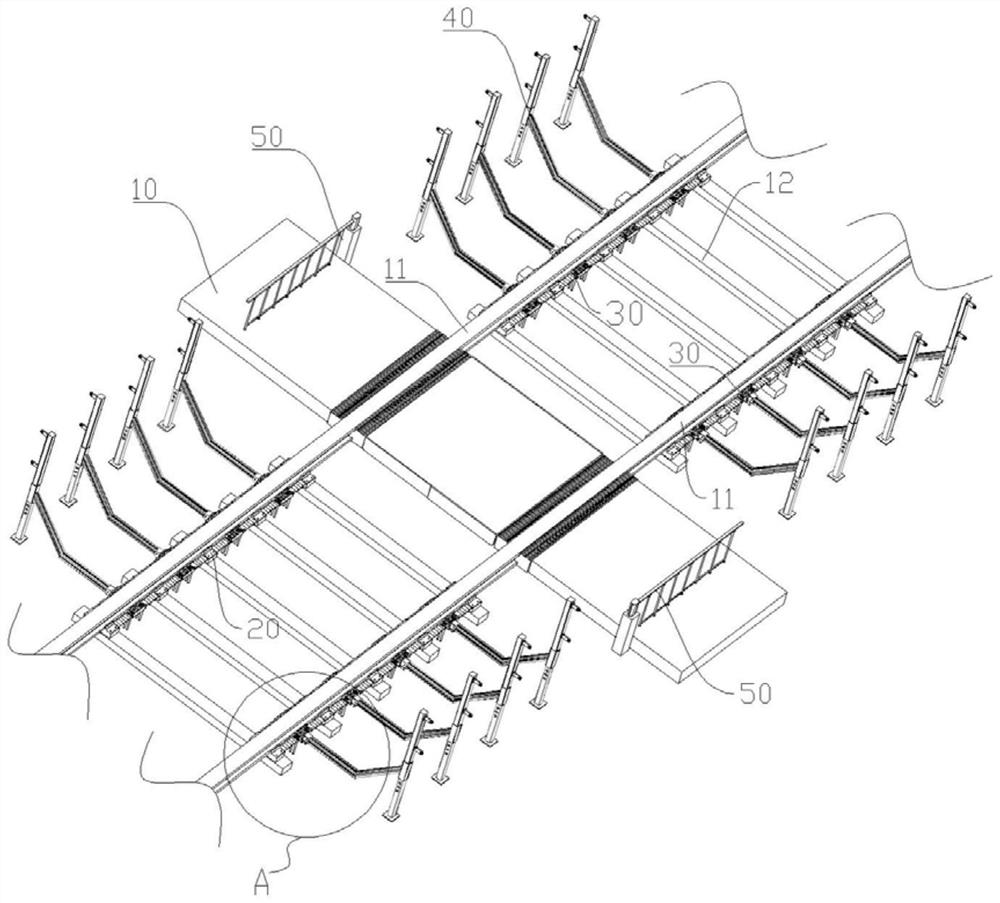
[0050] Figure 1 to Figure 5 A safe and stable rail protection device according to an embodiment of the present invention is schematically shown. As shown in the figure, the device is provided with a base 10 at a railway level crossing, the rails of the railway pass through the base 10, and side baffles are provided on both ends of the base 10 along the direction of the rails to strengthen the connection to the main body of the base 10. Protect. Reinforcing rails 11 are provided on both sides of the base 10 along the direction of the railway, and travel limiting components 50 are provided on both sides of the base 10 along the road.

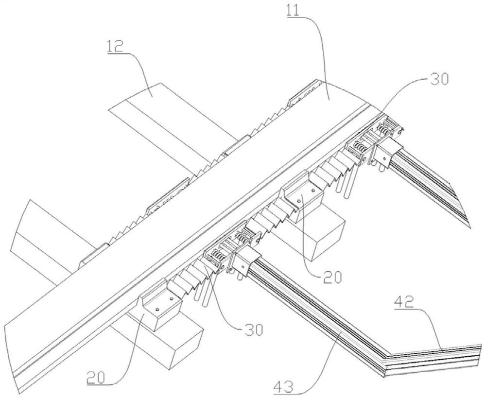
[0051] Specifically, reinforced rails 11 are provided on both sides of the base 10 along the direction of the railway. The bottom of the reinforced rail 11 is provided with a plurality of sleepers 12 arranged side by side. connect. Compared with the sleepers 12 in the main railway area, the sleepers 12 disposed under the reinforced rails 11 ha...

Embodiment 2

[0064] Figures 6 to 9 Schematically shows the line restriction assembly 50 of the safe and stable track guard device according to another embodiment of the present invention, which is different from Example 1 in that:

[0065]An anti-collision structure 60 is provided on the rigid strut 53 of the line limiting assembly 50 . The anti-collision structure 60 includes a plurality of supporting blades 61 and a protective casing 62. The protective casing 62 is arranged on the outer side of the supporting blades 61; One end is connected with the rigid strut 53 through the shaft sleeve 63 , and the other end of the supporting blade 61 is connected with the inner wall of the protective casing 62 . The supporting blade 61 and the protective casing 62 can rotate synchronously with the rigid strut 53 as the axis.

[0066] A plurality of ventilation through holes 64 are evenly distributed on the side wall of the protective shell 62 , and a bag 65 is provided at one end of the supporting...


PUM


Abstract

The safe and stable rail protection device comprises a base station arranged at a railway level crossing, reinforcing rails are arranged on the two sides of the base station in the railway direction, and traffic control assemblies are arranged on the other two sides of the base station; the lower portion of the reinforcing rail is connected with the top of the sleeper through a transition connecting base body. A limiting buffering assembly attached to the side face of the bottom of the reinforcing rail is arranged between every two adjacent sleepers, the transition connecting base body is provided with an assembling groove, the reinforcing rail is embedded in the assembling groove, and the two sides of the reinforcing rail are matched with limiting protrusions on the two sides of the assembling groove respectively. The limiting buffering assembly comprises two movable plate bodies arranged side by side, two springs are arranged between the two movable plate bodies side by side, a rubber column is arranged between the two springs, one end of the rubber column is connected with one movable plate body, and the other end of the rubber column abuts against the reinforcing rail. According to the sleeper, the situation that force transmitted downwards is too concentrated can be avoided, the problem that stress on the sleeper is too large is solved, and deformation and displacement of the rail due to stress can be avoided.

Description

technical field [0001] The invention belongs to the technical field of rail perimeter protection, in particular to a safe and stable rail protection device. Background technique [0002] The level crossing of railway and road is usually called railway level crossing, or crossing for short. The road at the crossing is generally made of reinforced concrete pavement, stone or wood. According to traffic volume and lookout conditions, crossings are divided into two types: protected crossings and unprotected crossings. A guarded crossing refers to a crossing equipped with protective equipment and sent to guard. The protective equipment used for crossings mainly includes crossing signal equipment, automatic fences, fence gates, etc., and if necessary, set up signal machines to interrupt color lights. [0003] Vehicles in rail transit cannot decelerate and avoid in time like road traffic, so people need to be isolated on rail transit tracks to ensure the safety of people and the ...

Claims


Application Information

Patent Timeline
IPC IPC(8): E01B2/00E01F15/00E01B19/00F16F15/08B61L29/04
CPCE01B2/00E01F15/00E01B19/003F16F15/085B61L29/04Y02A30/30
Inventor 李克非蒋倩劳慈航郭保稳臧宏润董源王佳车咏馨
Owner 北京航天长城卫星导航科技有限公司
Why Eureka
Try Eureka