
Pump for simulating physiological blood flow of patient

A patient and fluid technology, applied in the direction of blood pumps, blood pumps, pumps with flexible working elements, etc., can solve impractical problems

Pending Publication Date: 2022-06-21
TRIPHASIC CARDIAC PUMP PTY LTD
View PDF1 Cites 0 Cited by
  • Summary
  • Abstract
  • Description
  • Claims
  • Application Information

AI Technical Summary

Problems solved by technology

[0007] Another disadvantage of centrifugal heart pumps used in surgery is that the pump head is usually single-use because it is impractical to completely remove all blood residue from the pump
That means heart surgery costs a fortune

Method used


Image

  • Pump for simulating physiological blood flow of patient
  • Pump for simulating physiological blood flow of patient
  • Pump for simulating physiological blood flow of patient

Examples


Embodiment Construction

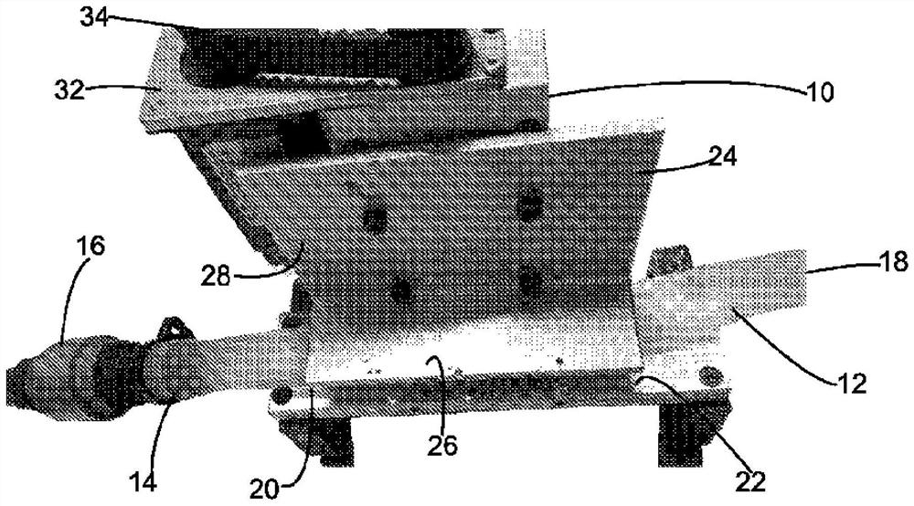
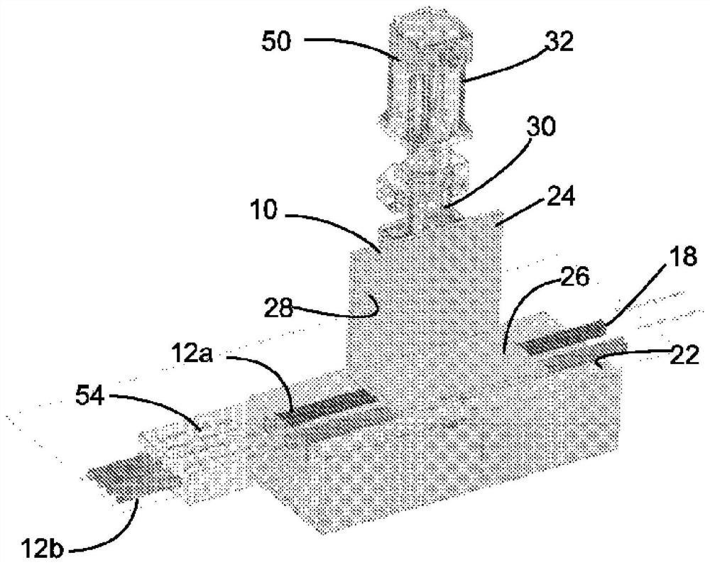
[0031] The first embodiment of the present invention, namely the pump 10, is as figure 1 and figure 2 shown. The pump 10 is arranged to pass fluid (in theory, blood) through the tube 12 . In this example, the tube 12 is formed from a platinum-coated silicone tube with an inner diameter of 19 mm. It is generally believed that biocompatible tubing with an inner diameter between 6mm and 25mm may be suitable for this purpose.

[0032] The tube 12 has an inlet 14 associated with a one-way valve 16 . The tube 12 also has an outlet 18 . Between the inlet 14 and outlet 18 of the tube is the operating portion 20 .

[0033] The operating portion 20 is arranged to abut against the rigid base plate 22 . A substantially L-shaped actuator 24 is placed along the operating portion 20 .

[0034] The actuator 24 has an actuating member, which is a pressure plate 26 , which is substantially horizontal and parallel to the base plate 22 . The actuator 24 has a support plate 28 perpendicul...


PUM


Abstract

The invention discloses a pump for simulating physiological blood flow of a patient. The pump works by compressing and decompressing the conduit to create a peristaltic flow within the conduit. The compression may be effected by a linear actuator or a rotating press. And a one-way check valve is adopted to ensure one-way flow.

Description

technical field [0001] The present invention relates to a pump. The pump was created for medical purposes and is configured to be used as part of a cardiopulmonary bypass profusion system or extracorporeal membrane oxygenation system to provide blood flow, or to treat critical organ hypoxia Provide blood flow. Furthermore, the pump can be configured to function as an artificial heart. The pump also has wider application, eg, in industrial applications, it can be programmed to dose a predetermined amount of fluid or semi-solid material into a container according to a desired filling profile. Background technique [0002] There are generally two types of heart pumps used in surgery: peristaltic and centrifugal. Both types of pumps can provide consistent flow of blood at appropriate pressures. The pump can be adjusted to compensate for changes in flow rate or pressure requirements. [0003] Traditional peristaltic and centrifugal pumps provide pulsatile or continuous blood...

Claims


Application Information

Patent Timeline
Patent Type & Authority Applications(China)
IPC IPC(8): A61M1/36A61M60/38A61M60/40A61M60/148A61M60/178
CPCA61M60/279F04B43/09A61M2205/3334F04B43/0072A61B2017/00398F04B43/12A61M60/857A61M60/569A61M60/538A61M60/515F04B43/082F04B43/1223F04B43/086A61M60/109A61M60/284A61M60/446A61M60/508A61M60/38A61M60/835A61M60/117A61M60/851A61M60/443A61M60/104A61M60/562A61M60/31
Inventor 艾尔伯特.允松.宋
Owner TRIPHASIC CARDIAC PUMP PTY LTD
Learn More