Cup chuck of substrate holding device and substrate holding device

A substrate holding and chucking plate technology, which is applied in the direction of semiconductor devices, electrolytic components, circuits, etc., can solve the problems of affecting product yield, prone to damage, and low thickness of electroplating layer, so as to improve convenience and efficiency and reduce damage Risk, the effect of reducing the exposed area

Pending Publication Date: 2022-06-21
ACM RES SHANGHAI
View PDF0 Cites 1 Cited by
  • Summary
  • Abstract
  • Description
  • Claims
  • Application Information

AI Technical Summary

Problems solved by technology

For example: 1) such as Figure 18 As shown, the electroplating fixture adopts all wrapped seals 23, the exposed area is too large, the outer surface 231 and the bottom surface 233 are prone to damage, especially at the bottom bending part 232, after the seal 23 is damaged, the electroplating solution penetrates the seal 23 Contact with the internal metal base 22 will cause partial loss of current, making the thickness of the electroplating layer on the substrate lower than the predetermined target value, affecting product yield
2) The sealing member 23 wraps a relatively hard metal base 22 inside, and the bottom of the metal base 22 is bent upwards to form a supporting part 221, which is only 1mm thick and very sharp. The sealing member 23 wraps the supporting part 221 to form a sealing lip 234. Among them, the sealing lip 234 is in close contact with the substrate through pressure to realize the sealing of the edge of the substrate and the back surface. However, the sealing lip 234 is prone to aging and cracking due to long-term stress.
3) The contact ring 25 and the seal 23 need to be cleaned during maintenance of the electroplating fixture. However, the internal pressure ring 24 and the contact ring 25 of the existing electroplating fixture are directly conductive, and there is no seal between the outer metal substrate 22, and the online During spray cleaning or immersion cleaning, the cleaning solution or plating solution will Figure 18 The arrow shown penetrates into the inner layer of the electroplating fixture, which cannot achieve the purpose of quick cleaning and maintenance, and needs to be disassembled separately for maintenance

Method used


Image

  • Cup chuck of substrate holding device and substrate holding device
  • Cup chuck of substrate holding device and substrate holding device
  • Cup chuck of substrate holding device and substrate holding device

Examples


Embodiment Construction

[0070] In order to describe the technical content, structural features, achieved objects and effects of the present invention in detail, the following will be described in detail with reference to the embodiments and the drawings.

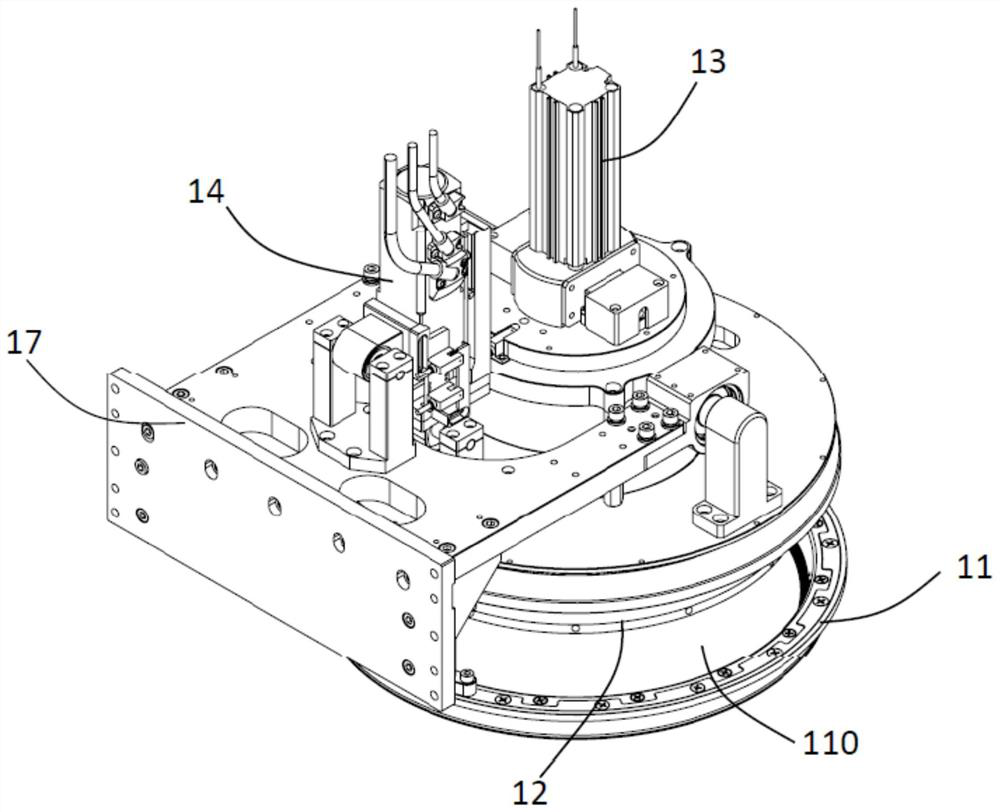
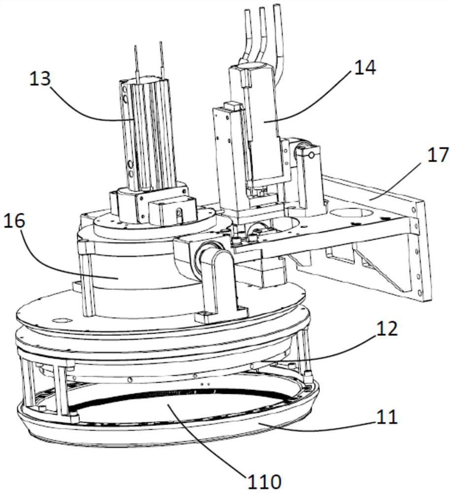
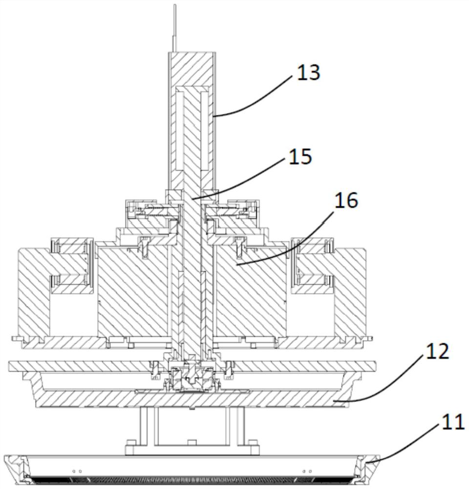
[0071] figure 1 and figure 2 A substrate holder in an embodiment of the present invention is shown. The substrate holding device includes components such as a cup chuck 11 , a chuck plate 12 , a chuck plate drive device 13 , an angle drive device 14 , a rotation drive device 16 , and a vertical drive device. A penetrating accommodating space 110 is formed in the center of the cup-shaped chuck 11 , and the accommodating space 110 is used for accommodating the substrate 10 . The chuck plate driving device 13 is connected to the chuck plate 12 through the universal joint shaft 15 to drive the chuck plate 12 to ascend and descend. Specifically, see image 3 , the chuck plate 12 is lifted to the substrate loading / unloading position away from the c...


PUM

PropertyMeasurementUnit
widthaaaaaaaaaa
widthaaaaaaaaaa
surface roughnessaaaaaaaaaa

Abstract

The invention discloses a cup-shaped chuck of a substrate holding device. The cup-shaped chuck comprises an inner pressing ring, a middle framework, a sealing piece, an outer pressing ring and a contact ring, and the inner pressing ring is locked on the inner circumferential surface of the middle framework. The sealing piece is provided with an outer end, a bottom and an inner end, the outer end of the sealing piece wraps at least part of the outer circumferential face of the middle framework, the bottom of the sealing piece wraps the bottom of the middle framework and is exposed out of the cup-shaped chuck, and the inner end of the sealing piece wraps at least part of the inner circumferential face of the middle framework and is exposed out of the cup-shaped chuck. And the inner end part of the sealing piece is tightly pressed between the inner pressing ring and the middle framework through the inner pressing ring. The outer pressing ring is made of insulating materials and is locked on the peripheral face of the middle framework, and the outer end of the sealing piece is pressed between the outer pressing ring and the middle framework through the outer pressing ring. The contact ring is located on the sealing piece and connected between the inner pressing ring and the middle framework in a pressed mode, and a sealing ring is arranged between the inner pressing ring and the contact ring.

Description

technical field [0001] The present invention relates to the technical field of semiconductor electroplating, and more particularly, to a cup-shaped chuck for holding a substrate during electroplating and a substrate holding device. Background technique [0002] The electroplating fixture that holds the substrate is an important part of the semiconductor electroplating equipment. The electroplating fixture is usually equipped with a contact ring and a seal, and the seal is used to isolate the electroplating solution from the contact ring, so as to avoid the uneven electroplating film caused by poor contact between the contact ring and the seed layer. Therefore, the performance of the seal is a key factor in ensuring the normal operation of the electroplating process. [0003] At present, there are still many problems in the long-term use of the seals in the electroplating fixture. For example: 1) as Figure 18 As shown, the electroplating fixture adopts all wrap-type seals ...

Claims


Application Information

Patent Timeline
Patent Type & Authority Applications(China)
IPC IPC(8): C25D17/08C25D7/12
CPCC25D17/08C25D7/12C25D17/001
Inventor 王晖王坚贾照伟金一诺杨宏超
Owner ACM RES SHANGHAI
Why Eureka
Try Eureka