Accurate synchronization method of transient recording type fault indicator

A fault indicator, accurate synchronization technology, applied in the direction of synchronization, clocks driven by synchronous motors, instruments, etc., can solve problems such as inability to meet accurate synchronization, increase wireless transmission power consumption, time or temperature offset, etc. The effect of researching and judging accuracy, occupying less resources and improving stability

Active Publication Date: 2022-06-07
QINGDAO TOPSCOMM COMM
View PDF16 Cites 1 Cited by
  • Summary
  • Abstract
  • Description
  • Claims
  • Application Information

AI Technical Summary

Problems solved by technology

[0003] The clocks of such embedded devices use different crystal oscillators to have different accuracy, but for crystal oscillators, they will all drift with time or temperature, which will amplify the error clock error for devices that require precise synchronization is not allowed, so clock synchronization is required to reduce this error
[0004] According to the regulations, the accuracy of the fault indicator of transient recording type should be within 100us. At present, the common method of clock synchronization is to shorten the synchronous time calibration cycle, and the time is corrected every second or tens of milliseconds, which greatly increases the power consumption of wireless transmission. , and some even find another way to use GPS to adjust the time, which cannot meet the precise synchronization under ultra-low power consumption

Method used


Image

  • Accurate synchronization method of transient recording type fault indicator
  • Accurate synchronization method of transient recording type fault indicator
  • Accurate synchronization method of transient recording type fault indicator

Examples


Embodiment Construction

[0022] In order to make the objectives, technical solutions and advantages of the present invention clearer, the present invention will be further described in detail below with reference to the accompanying drawings and embodiments. It should be understood that the specific embodiments described herein are only used to illustrate the present invention, but not to limit the present invention.

[0023] Assuming that the fault indicator acquisition unit and the fault indicator collection unit use a low-frequency 32768Hz crystal oscillator, the calibratable accuracy is (1 / 32768)us, which is approximately equal to 30.5us, and the clock offset is fixed within one clock cycle, which is the synchronization accuracy target. within 30.5us.

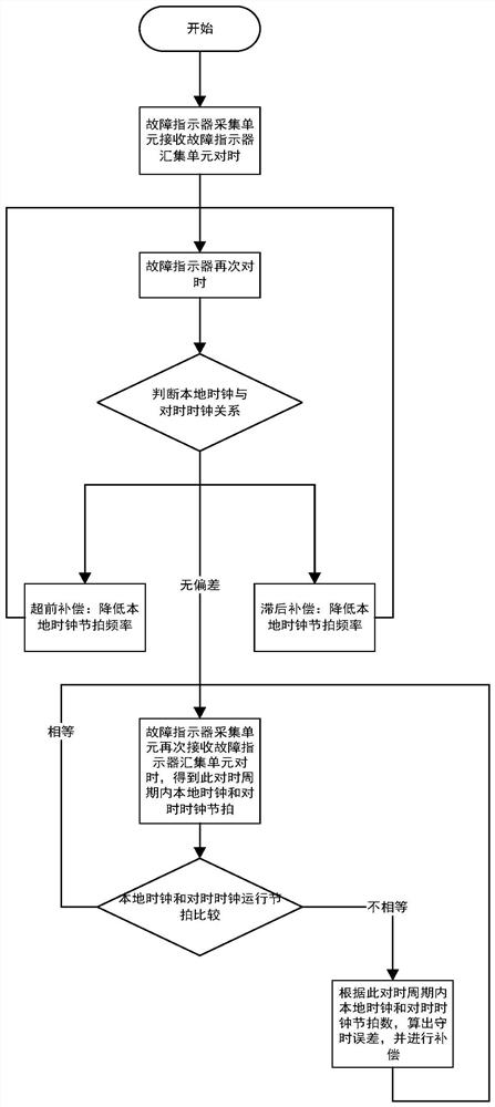
[0024] like figure 1 As shown in the figure, a precise synchronization method of a transient recording type fault indicator specifically includes the following steps:

[0025] Step 1: According to the one-master multi-slave mode of the transient ...


PUM


Abstract

The invention discloses an accurate synchronization method of a transient recording type fault indicator, which comprises the following steps of: receiving time synchronization of a fault indicator collection unit through a fault indicator acquisition unit, calculating the rhythm of a local clock and a time synchronization clock in a time synchronization period, comparing, carrying out lead or lag compensation, and if the rhythm numbers are consistent, carrying out time synchronization. If yes, the beat matching error is reduced to the minimum. And if the condition that the beat number of the local clock and the beat number of the time synchronization clock in the time synchronization period are inconsistent occurs again, the crystal oscillator offset error is calculated and compensated, and the synchronization error is reduced to be within one clock period by calibrating the beat matching error and the crystal oscillator offset error. The method is simple and reliable, occupies few resources, is high in adaptive capacity, realizes accurate synchronization of the transient wave recording type fault indicator, increases the fault waveform research and judgment accuracy, improves the power supply stability of a power grid, and is of great significance in maintaining a reliable power utilization environment.

Description

technical field [0001] The invention relates to a medium-voltage distribution network technology, in particular to a precise synchronization method of a transient recording type fault indicator. Background technique [0002] The transient recording type fault indicator is a typical one-master multi-slave embedded device that requires low power consumption and high precision. The indicator collection unit has three fault indicator collection units. The fault indicator acquisition unit collects the current and electric field of the line. When the line is abnormal, the fault indicator acquisition unit triggers the recording and transmits the real-time collected data to the fault indicator collection unit, which then uploads the waveform to the fault indicator collection unit through 4G. Main station research. The fault indicator collection unit calibrates the fault indicator acquisition unit, so that each fault indicator acquisition unit realizes the synchronization of the sa...

Claims


Application Information

Patent Timeline
Patent Type & Authority Applications(China)
IPC IPC(8): G04G7/00
CPCG04G7/00Y04S10/52
Inventor 范建华姚兴东唐铸赵传强赵磊王建辉杨顺徐东杰
Owner QINGDAO TOPSCOMM COMM
Why Eureka
Try Eureka