Pile plate retaining wall structure suitable for filling side slope and construction method

A pile plate and retaining wall technology, which is applied in basic structure engineering, sheet pile walls, underwater structures, etc., can solve the problems of high scrap rate of formwork, weak pouring of broken piles, unsafe structure, etc., so as to shorten the construction period and ensure reliability. The effect of high connection and structural reliability

Pending Publication Date: 2022-06-07
POWER CHINA KUNMING ENG CORP LTD
View PDF0 Cites 2 Cited by
  • Summary
  • Abstract
  • Description
  • Claims
  • Application Information

AI Technical Summary

Problems solved by technology

[0006] The purpose of the present invention is to provide a pile-slab retaining wall structure suitable for filling slopes and its construction method, which can solve the problem of pouring weak surfaces of broken piles in the construction of circular cross-section anti-slide piles; The slab has problems such as extended construction period due to waiting for concrete strength, unsafe structure caused by planting bars, and high formwork scrap rate caused by pre-embedded steel bars; and it can solve the unreliable connection between prefabricated retaining slabs and circular cross-section anti-slide piles question

Method used


Image

  • Pile plate retaining wall structure suitable for filling side slope and construction method
  • Pile plate retaining wall structure suitable for filling side slope and construction method
  • Pile plate retaining wall structure suitable for filling side slope and construction method

Examples


Embodiment Construction

[0040] Now refer to the attached Figure 1 to Figure 6 Embodiments of the present invention are described. Those skilled in the art will understand that the following examples are only used for the patent of the present invention and should not be regarded as limiting the scope of the present invention. If the specific technology, connection relationship or condition is not indicated in the embodiment, the technology, connection relationship and conditions described in the literature in the field shall be followed or the product specification and specification shall be followed. The materials, instruments or equipment used without the manufacturer's indication are conventional products that can be obtained through purchase.

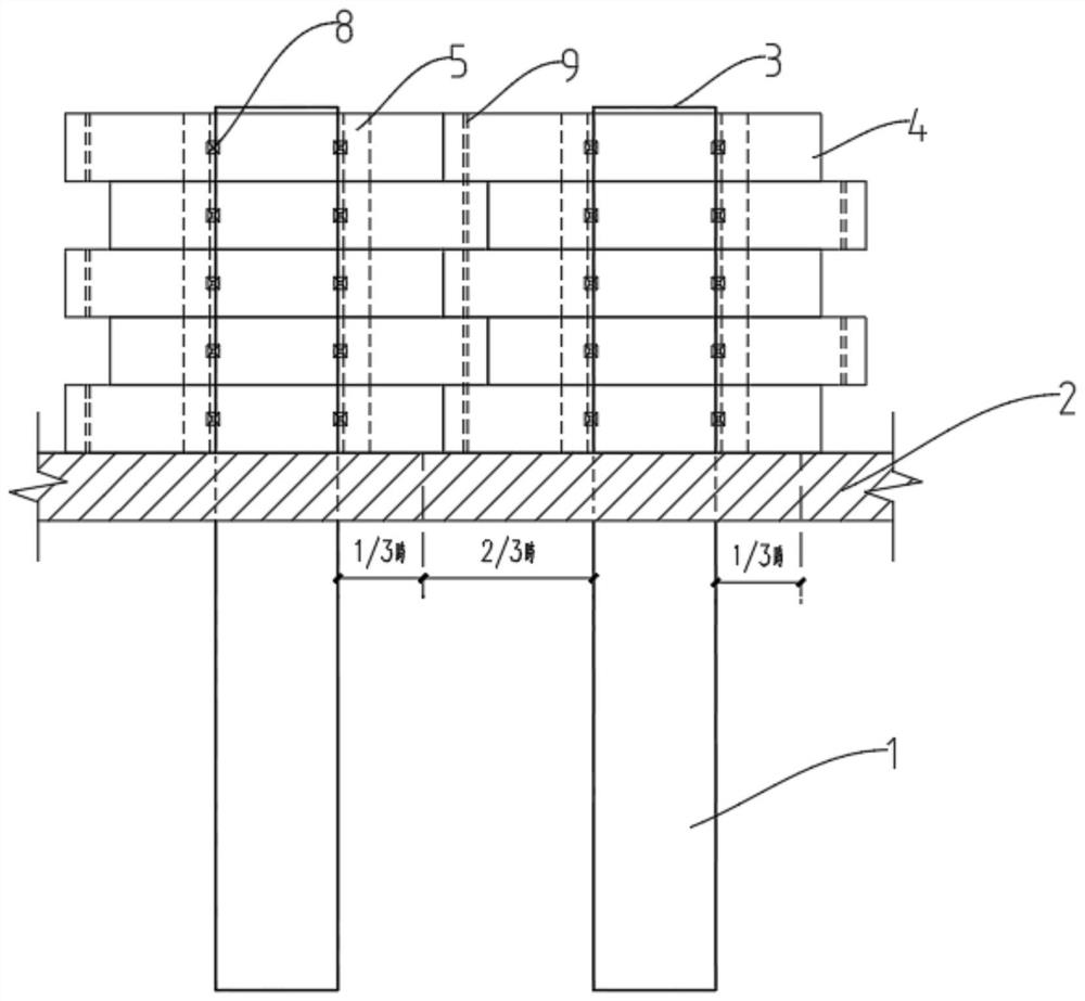
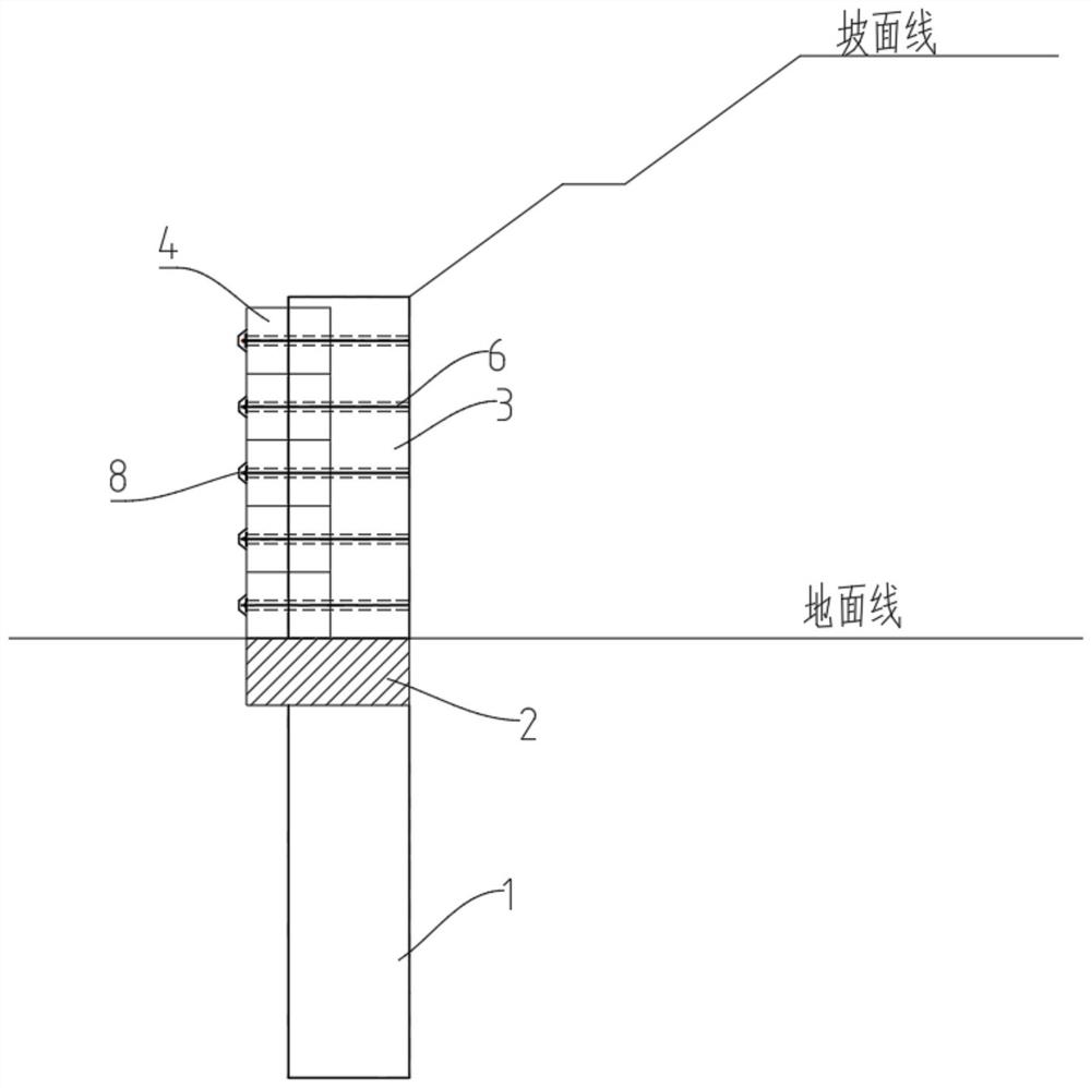
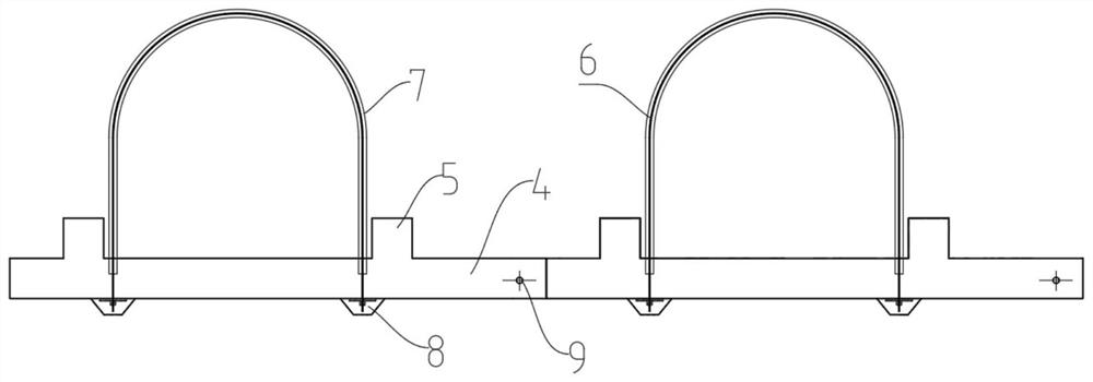
[0041] combine Figures 1 to 6 As shown in the figure, the present invention discloses a pile-plate retaining wall structure suitable for filling slopes. According to the force characteristics of the anchorage and the retaining plate, the present invent...


PUM


Abstract

The invention belongs to the technical field of supporting and retaining structure design in geotechnical engineering, and particularly discloses a pile plate retaining wall structure suitable for a fill slope and a construction method thereof.The pile plate retaining wall structure comprises an underground anti-slide pile, an overground anti-slide pile, a connecting beam and a prefabricated soil retaining plate, the underground anti-slide pile is arranged below the ground line and is in a cylinder shape, and the overground anti-slide pile is arranged below the ground line; the ground anti-slide pile is arranged above a ground line and is integrally a column body, the soil retaining side is arc-shaped, the free side is rectangular, a connecting beam is arranged at the junction of the underground anti-slide pile and the ground line, the prefabricated soil retaining plate is arranged on the rectangular side of the ground anti-slide pile, rectangular limiting blocks are fixedly arranged on the two sides of the ground anti-slide pile, and the prefabricated soil retaining plate is arranged on the ground anti-slide pile. The connecting beams are arranged at the joints of the piles and the ground, reinforcement of broken pile pouring of the ground up-down anti-slide piles is achieved, and the structural reliability is enhanced.

Description

technical field [0001] The patent of the invention belongs to the technical field of retaining structure design in geotechnical engineering, and particularly provides a pile-plate retaining wall structure suitable for filling slopes and a construction method thereof. Background technique [0002] Pile-sheet retaining wall is a commonly used support structure in geotechnical engineering fill slopes, especially for tall and large fill slopes. Compared with rectangular cross-section anti-sliding piles, circular cross-section anti-sliding piles have the characteristics of faster construction speed and less potential safety hazards. With the development of technical level and the requirements of project construction period, more and more circular cross-section anti-sliding piles have been replaced Rectangular anti-slide pile. [0003] Due to the mechanical construction, the circular section piles have no concrete wall protection measures. In order to ensure the quality of the pi...

Claims


Application Information

Patent Timeline
IPC IPC(8): E02D29/02E02D5/34
CPCE02D29/02E02D29/0283E02D5/34Y02A10/23
Inventor 陈琳饶学治韦巍王晶涛李小膀高如李林锋
Owner POWER CHINA KUNMING ENG CORP LTD
Why Eureka
Try Eureka