System monitoring device based on CPLD

A system monitoring and system-under-test technology, applied in hardware monitoring, generation of response errors, error detection of redundant data in operations, etc. And other issues

Pending Publication Date: 2022-06-03
武汉迈威通信股份有限公司
View PDF0 Cites 0 Cited by
  • Summary
  • Abstract
  • Description
  • Claims
  • Application Information

AI Technical Summary

Problems solved by technology

[0002] At present, the application of processors is becoming more and more complex, which brings many challenges. How to ensure the stable operation of the system in different working environments is a major difficulty. Among them, the monitoring system plays an increasingly important role. like figure 1 As shown, the traditional system monitoring method is generally implemented by using an external watchdog, and the GPIO (General Purpose Input Output, general purpose input / output port) derived from the processor continuously sends a feeding signal to the WDI pin of the watchdog chip, When the device fails, the processor stops feeding the dog, which triggers the watchdog chip to restart the system. However, this method has many defects. Sometimes the power-on sequence is disordered due to external strong electromagnetic interference during the power-on process of the device, resulting in The processor cannot be started. At this time, the external watchdog has not started to work, and the processor cannot be reset, which will cause the device to crash. In addition, if the device has a hardware failure, no matter how the external watchdog restarts the system, the device cannot be reset. Return to normal, and there is no corresponding measure to quickly power off the equipment and inform the equipment maintenance personnel of the fault information in time

Method used


Image

  • System monitoring device based on CPLD

Examples


Embodiment Construction

[0015] The specific embodiments of the present invention will be described in further detail below with reference to the accompanying drawings and embodiments. The following examples are intended to illustrate the present invention, but not to limit the scope of the present invention.

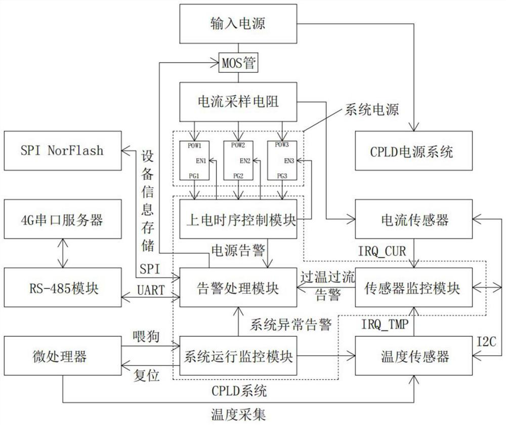
[0016] Based on the defects in the background technology, the present invention provides a high-efficiency system monitoring device based on CPLD, which can perfectly solve the above problems. Choose to turn off the system power or control the power-on sequence, and the system also monitors the onboard sensors, which can turn off the power in time and send alarm information to equipment maintenance personnel when a hardware failure occurs in the system. In addition, the system monitoring device also has the function of external watchdog, which can perform hot restart and cold restart of the system when the system equipment fails, and power off the equipment in time if the restart is invalid. T...


PUM


Abstract

The invention provides a system monitoring device based on a CPLD (Complex Programmable Logic Device). The system monitoring device comprises a power-on time sequence control module, a sensor monitoring module, a system operation monitoring module and an alarm processing module, the power-on time sequence control module is used for monitoring all power supply chips of the tested system; the sensor monitoring module is used for monitoring the working current and the working temperature of the tested system, and when the working current or the working temperature is abnormal, the alarm processing module is notified to turn off the system power supply; and the system operation monitoring module is used for monitoring the operation state of the tested system and informing the alarm processing module to perform soft reset operation or power-off restart operation on the tested system or turn off the system power supply if the system is abnormal. According to the invention, the tested system is monitored based on the CPLD, so that the monitored system can be automatically recovered when a software fault occurs, and can be timely powered off when a hardware fault occurs.

Description

technical field [0001] The present invention relates to the field of system monitoring, and more particularly, to a system monitoring device based on CPLD. Background technique [0002] At present, the application of processors is becoming more and more complex, which also brings many challenges. How to ensure that the system can run stably in different working environments is a major difficulty. Among them, the monitoring system plays an increasingly important role. like figure 1 As shown in the figure, the traditional system monitoring method is generally implemented by an external watchdog. The GPIO (General Purpose Input Output, general input / output port) derived from the processor continuously sends a dog feeding signal to the WDI pin of the watchdog chip. When the device fails, the processor stops feeding the dog, thereby triggering the watchdog chip to restart the system. However, there are many defects in this method. Sometimes the power-on sequence is chaotic due t...

Claims


Application Information

Patent Timeline
IPC IPC(8): G06F11/14G06F11/30
CPCG06F11/1441G06F11/3058Y02D10/00
Inventor 张朋飞蔡飞周厚明
Owner 武汉迈威通信股份有限公司
Why Eureka
Try Eureka