Bridge crane time/energy optimal trajectory planning method and system
An energy-optimized technology for overhead cranes, applied in control/regulation systems, general control systems, instruments, etc., can solve problems such as the optimization of operating time and energy consumption for lifting liquid loads by overhead cranes
- Summary
- Abstract
- Description
- Claims
- Application Information
AI Technical Summary
Problems solved by technology
Method used
Image
Examples
Embodiment 1
[0049] This embodiment provides a time / energy optimal trajectory planning method for an overhead crane.
[0050] A time / energy optimal trajectory planning method for an overhead crane, comprising:
[0051] Obtain trolley data, container data, liquid data and rope data;
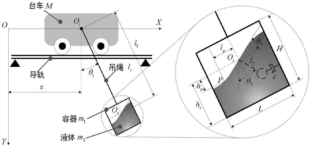
[0052] Based on the trolley data, container data, liquid data and suspension rope data, the Lagrangian method is used to establish the dynamic model of the overhead crane system for suspending the liquid container;
[0053] On the premise of considering the driving state constraints and non-driving state constraints, using the convex optimization theory and according to the dynamic model, the problem of trajectory planning of the bridge crane is transformed into an optimal control problem;
[0054] Design the optimal trajectory with the goal of the shortest transportation time or the least energy consumption or the optimal time-energy;
[0055] Accurate positioning and sway suppression control of the bridge ...
Embodiment 2
[0165] This embodiment provides a time / energy optimal trajectory planning system for an overhead crane.
[0166] A time / energy optimal trajectory planning system for an overhead crane, comprising:
[0167] A data acquisition module configured to: acquire trolley data, container data, liquid data and sling data;
[0168] A model building module configured to: establish a dynamics model of an overhead crane system with a suspended liquid container based on the trolley data, the container data, the liquid data, and the sling data, using a Lagrangian method;
[0169] A model transformation module, which is configured to convert the trajectory planning problem of the bridge crane into an optimal control problem according to the dynamic model by using the convex optimization theory under the premise of considering the driving state constraint and the non-driving state constraint;
[0170] An optimal design module, which is configured to: design an optimal trajectory with the shorte...
Embodiment 3
[0174] This embodiment provides a computer-readable storage medium, on which a computer program is stored, and when the program is executed by a processor, the steps in the time / energy optimal trajectory planning method for an overhead crane as described in the first embodiment above are realized .
PUM
 Abstract
Description
Claims
Application Information
 - Generate Ideas
- Intellectual Property
- Life Sciences
- Materials
- Tech Scout
- Unparalleled Data Quality
- Higher Quality Content
- 60% Fewer Hallucinations
Browse by: Latest US Patents, China's latest patents, Technical Efficacy Thesaurus, Application Domain, Technology Topic, Popular Technical Reports.
© 2025 PatSnap. All rights reserved.Legal|Privacy policy|Modern Slavery Act Transparency Statement|Sitemap|About US| Contact US: help@patsnap.com


