
Raman temperature measurement radar boundary layer identification method

An identification method and Raman temperature measurement technology, applied in thermometers, heat measurement, measurement devices, etc., can solve problems such as misjudgment and misjudgment, fluctuation of single signal strength, etc., and achieve the effect of high accuracy, good real-time performance and flexible constraints

Pending Publication Date: 2022-06-03
无锡中科光电技术有限公司
View PDF0 Cites 0 Cited by
  • Summary
  • Abstract
  • Description
  • Claims
  • Application Information

AI Technical Summary

Problems solved by technology

[0006] Lidar signal boundary layer recognition can be divided into single profile judgment and combined spatio-temporal information judgment. Spatio-temporal calculations mostly use graphic algorithms, which has the advantage of being able to combine more information to eliminate some interference; the calculation of a single profile has good real-time performance and usually relies on the slope The distance square correction strength slope change position is calculated by the distance square method as the boundary layer, but because the single signal strength fluctuates obviously, it is easy to cause misjudgment and misjudgment

Method used


Image

  • Raman temperature measurement radar boundary layer identification method
  • Raman temperature measurement radar boundary layer identification method
  • Raman temperature measurement radar boundary layer identification method

Examples


Embodiment Construction

[0016] In order for those skilled in the art to better understand the technical solutions of the present invention, and to make the above-mentioned features, purposes and advantages of the present invention more clearly understood, the present invention will be further described below with reference to the embodiments. The examples are only used to illustrate the present invention and not to limit the scope of the present invention.

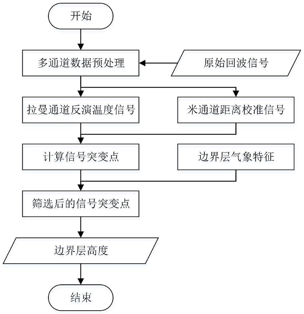
[0017] like figure 1 As shown, the present invention comprises the following steps:

[0018] The first step: preprocess the original Raman radar signal of vertical detection, invert the Raman signal to obtain the vertical temperature profile, and use the zero-order distance square correction signal as the verification signal;

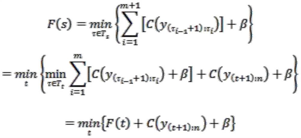
[0019] Step 2: Use piecewise first-order linear fitting for the two processed signals, calculate and obtain the temperature profile and verify that the signal is divided into segmented line segments, and use the least squ...


PUM


Abstract

The invention provides a Raman temperature measurement radar boundary layer identification method, which comprises the following steps of: 1, preprocessing a vertically detected Raman radar original signal, inverting a Raman signal to obtain a vertical temperature profile, and taking a zero-order distance square correction signal as a verification signal; step 2, carrying out segmented first-order linear fitting on the two processed signals, calculating to obtain a temperature profile and segment line segments divided by verification signals, and carrying out fitting calculation on a residual error by adopting a least square method; 3, identifying piecewise linear fitting piecewise points, namely signal abrupt change points, through a method of setting a residual threshold; and 4, determining the judgment result of the signal abrupt change point obtained in the step 3 by using the physical significance of the boundary layer height. The method is good in real-time performance and more flexible in constraint, depends on the high precision of the temperature profile, and verifies the rationality of the boundary layer by using the verification signal; in addition, the method does not depend on first-order and second-order derivatives, is not liable to be affected by signal quality and smoothing modes, and is not liable to erroneously judge the boundary layer height due to signal intensity fluctuation.

Description

technical field [0001] The invention mainly relates to the field of determining the height of the atmospheric boundary layer, in particular to a Raman temperature measuring radar boundary layer identification method. Background technique [0002] The vertical distribution of pollutants, the height of the boundary layer, and the atmospheric temperature are closely related. Under the condition of a certain source of pollutants, the accumulation, dilution, diffusion and removal of pollutants mainly depend on meteorological conditions. The increase of solar radiation, the increase of humidity, and the increase of the near-surface flow. The detection data show that the meteorological parameters (such as temperature, wind speed, humidity, etc.) on the upper and lower sides of the top of the boundary layer have obvious inflection points. At the same time, the pollution on the upper and lower sides The concentration of pollutants can differ by several times, so the height of the bou...

Claims


Application Information

Patent Timeline
Patent Type & Authority Applications(China)
IPC IPC(8): G01S17/95G01K11/00
CPCG01S17/95G01K11/006Y02A90/10
Inventor 曲洪丰潘浩陈晓龙
Owner 无锡中科光电技术有限公司
Learn More