
Self-aligning roller bearing used based on stirring equipment

A technology of self-aligning roller bearing and stirring equipment, which is applied in rolling contact bearings, rotating bearings, bearings, etc., can solve the problems of reducing the service life of the bearing, the heat cannot be dissipated in time, and the service life of the bearing is shortened, so as to prolong the service life. life, improve heat dissipation effect, improve service life effect

Active Publication Date: 2022-06-03
山东华工轴承有限公司
View PDF14 Cites 4 Cited by
  • Summary
  • Abstract
  • Description
  • Claims
  • Application Information

AI Technical Summary

Problems solved by technology

[0003] However, as far as the existing self-aligning roller bearings based on stirring equipment are concerned, since the bearings need to rotate at high speed while having self-aligning performance, the rollers in the bearings are in a state of friction for a long time, and the rollers are solid bodies. The internal heat of the rollers cannot be dissipated in time, and the rollers will be deformed and chipped due to heat, which will reduce the service life of the bearings, and dust and other particles will also enter the bearings from the gaps, because the dust and iron filings cannot be effectively cleaned , the rollers and the inner and outer rings of the bearing will wear faster and reduce the service life of the bearing

Method used


Image

  • Self-aligning roller bearing used based on stirring equipment
  • Self-aligning roller bearing used based on stirring equipment
  • Self-aligning roller bearing used based on stirring equipment

Examples


Embodiment

[0028] Example: please refer to Figure 1 to Figure 8 shown:

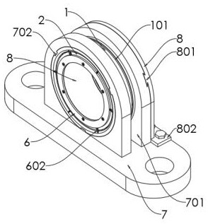
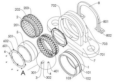
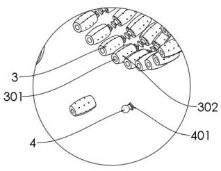
The present invention provides a self-aligning roller bearing based on stirring equipment, including a bearing outer ring 1; the bearing outer ring 1 is installed in a bearing seat 7, a fixing frame 8 is inserted on the right side wall of the bearing seat 7, and the inner part of the bearing outer ring 1 The cage 2 and the bearing inner ring 5 are sleeved. The cage 2 is arranged between the bearing outer ring 1 and the bearing inner ring 5. The cage 2 is rotatably connected with a heat dissipation roller 3, and a side wall of the heat dissipation roller 3 is connected There are ball heads 4, and ferrules 6 are installed on the left and right side walls of the inner ring 5 of the bearing. When in use, the spherical roller bearing has self-aligning performance, so it is not easily affected by shaft bending, and is suitable for installation errors or shaft deflection. When the angle error is caused, in addition to the...


PUM


Abstract

The invention provides a self-aligning roller bearing based on stirring equipment, and relates to the field of bearings. The bearing outer ring is installed in the bearing seat, the fixing frame is inserted into the right side wall of the bearing seat, the retainer and the bearing inner ring are sleeved with the bearing outer ring, the retainer is arranged between the bearing outer ring and the bearing inner ring, the heat dissipation roller is rotationally connected into the retainer, and the ball head is connected into one side wall of the heat dissipation roller. The lantern rings are mounted on the left side wall and the right side wall of the bearing inner ring, the heat dissipation rollers promote lubricating oil to flow in the heat dissipation rollers through the heat dissipation channels and the heat dissipation holes, heat is taken away by flowing through the heat dissipation holes while the heat dissipation rollers are lubricated, better heat dissipation of the bearing is facilitated, the heat dissipation effect of the bearing is improved, and the service life of the bearing is prolonged; the problems that the solid roller is in a friction state for a long time, internal heat cannot be dissipated in time, deformation and chip falling are prone to occurring, dust and other particulate matter cannot be effectively cleaned, and consequently the roller and the bearing inner and outer rings are rapidly abraded are solved.

Description

technical field [0001] The present invention relates to the technical field of bearings, in particular to a spherical roller bearing used based on stirring equipment. Background technique [0002] Spherical roller bearing is a kind of bearing with high radial load capacity and can also bear axial load in any direction, especially suitable for bearings working under heavy load or vibration load. Spherical roller bearing has two rows The rollers mainly bear radial loads. The two rows of rollers are installed between the inner ring with two raceways and the outer ring with spherical raceways to form a rolling connection. The outer raceway of the spherical roller bearing is spherical. , so its self-aligning performance is good, and it can compensate the coaxiality error. [0003] However, as far as the existing spherical roller bearings based on stirring equipment are concerned, since the bearings need to rotate at high speed while having self-aligning performance, the rollers ...

Claims


Application Information

Patent Timeline
IPC IPC(8): F16C23/08F16C33/36F16C33/58F16C33/66F16C33/46F16C33/48F16C33/78F16C35/077F16C37/00B08B1/04
CPCF16C23/082F16C33/36F16C33/583F16C33/6659F16C33/6681F16C33/48F16C33/467F16C33/581F16C33/7816F16C33/7803F16C35/077F16C37/007F16C2235/00B08B1/32B08B1/12Y02T10/86
Inventor 张宝中
Owner 山东华工轴承有限公司
Learn More