Surrounding rock lagging grouting reinforcement method suitable for high ground stress deep-buried soft rock tunnel

A technology of grouting reinforcement and high in-situ stress, which is applied in tunnels, tunnel linings, earth-moving drilling and mining, etc., can solve the problem of insufficient grouting depth and reinforcement range, insufficient bearing capacity of shallow loose surrounding rocks, and deep buried soft rock tunnels with high in-situ stress. Not applicable, etc.

Pending Publication Date: 2022-06-03
CHINA RAILWAY 12TH BUREAU GRP +2
View PDF0 Cites 0 Cited by
  • Summary
  • Abstract
  • Description
  • Claims
  • Application Information

AI Technical Summary

Problems solved by technology

If the grouting pressure is too low, the grout will only spread in the shallow surrounding rock behind the primary support, and the grouting depth and reinforcement range will not be enough; if the grouting pressure is too high, the shallow loose surrounding rock will have insufficient bearing capacity, and grouting and leakage will easily occur Slurry phenomenon, in severe cases, the primary support will be crushed
[0004] At present, in the actual engineering application of deep buried soft rock tunnels with high ground stress, the reinforcement timing of surrounding rock lagging grouting is mainly based on empirical analogy. Applicability, it is difficult to guarantee the grouting range and reinforcement effect, resulting in the large deformation of the support structure difficult to avoid during the construction of high ground stress deep soft rock tunnels

Method used


Image

  • Surrounding rock lagging grouting reinforcement method suitable for high ground stress deep-buried soft rock tunnel
  • Surrounding rock lagging grouting reinforcement method suitable for high ground stress deep-buried soft rock tunnel
  • Surrounding rock lagging grouting reinforcement method suitable for high ground stress deep-buried soft rock tunnel

Examples


Embodiment Construction

[0036] The technical solutions in the embodiments of the present invention will be clearly and completely described below. Obviously, the described embodiments are only a part of the embodiments of the present invention, rather than all the embodiments. Based on the embodiments of the present invention, all other embodiments obtained by those of ordinary skill in the art without creative efforts shall fall within the protection scope of the present invention.

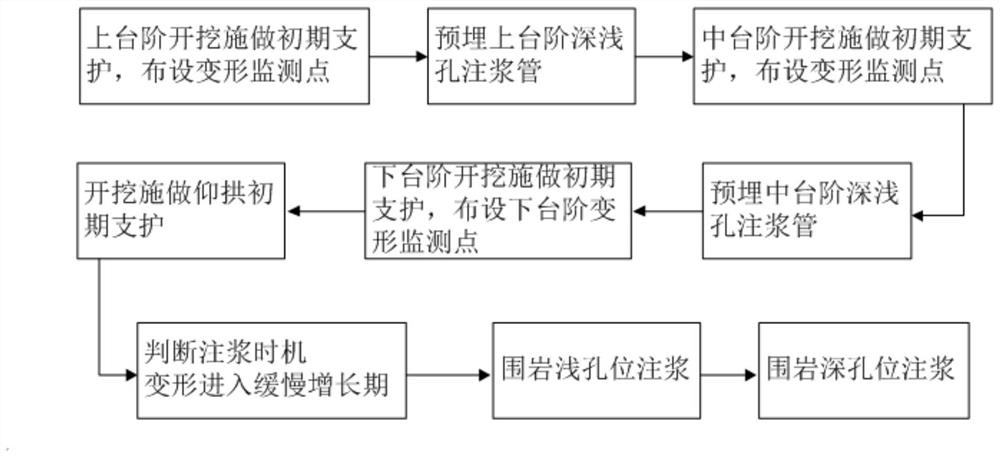
[0037] like Figure 1 to Figure 5 As shown, a surrounding rock lag grouting reinforcement method suitable for deep buried soft rock tunnels with high in-situ stress includes the following steps:

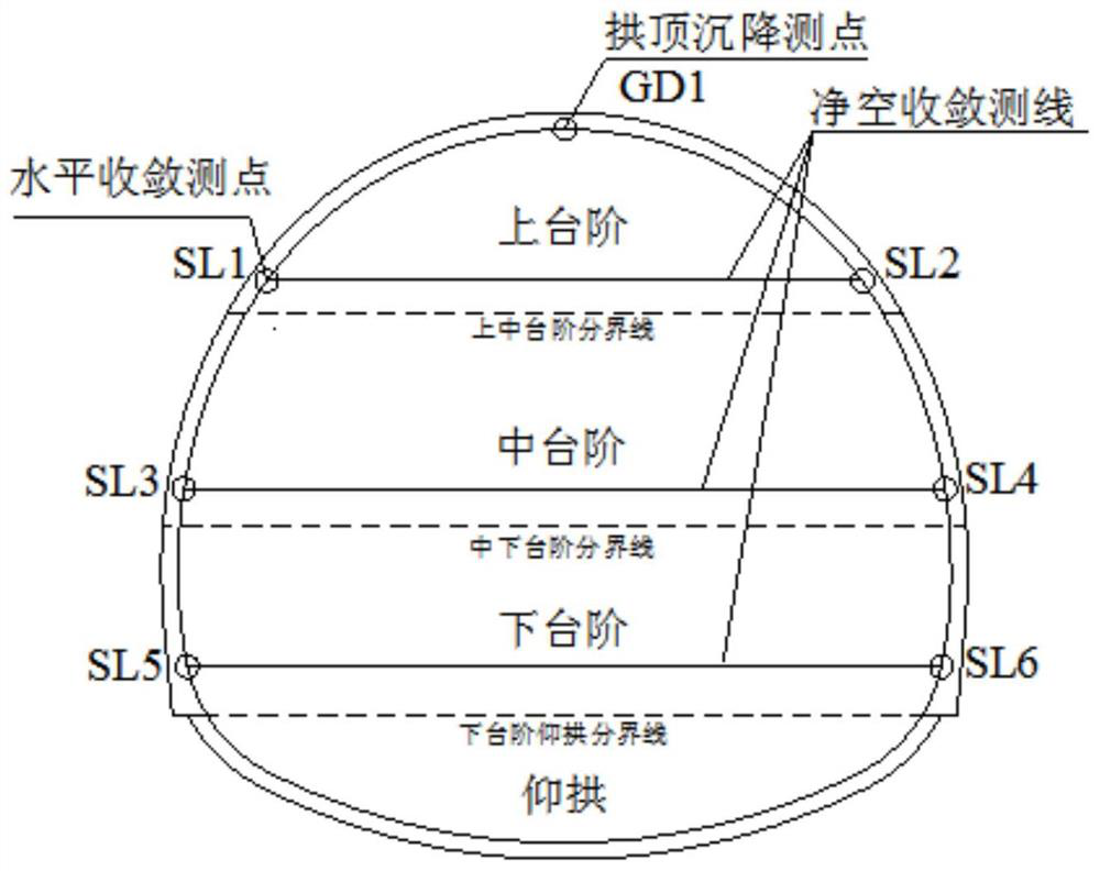
[0038] S1. Excavate the upper steps, and apply the initial support 1 for the upper steps. Initial support for the upper steps and the remaining sub-steps includes shotcrete, steel arches and system bolts. After the initial support of the upper step is completed, a monitoring section is set every 5m, and the deformation monit...


PUM


Abstract

The invention relates to the technical field of tunnel construction, in particular to a surrounding rock lagging grouting reinforcement method suitable for a high ground stress deep-buried soft rock tunnel. Comprising the following steps: excavating an upper step, initially supporting the upper step, and arranging an upper step monitoring point; setting out deep and shallow hole grouting positions of the upper step, and pre-embedding small grouting guide pipes; excavating a middle step, primarily supporting the middle step, and arranging a middle step monitoring point; setting out grouting positions of deep and shallow holes of the middle step, and pre-embedding small grouting guide pipes; excavating a lower step, primarily supporting the lower step, arranging a lower step monitoring point, and constructing an inverted arch primary support; after deformation enters a slow growth period, low-pressure grouting is conducted on shallow surrounding rocks; and after shallow surrounding rock grout forms a grout stopping barrier, deep surrounding rock high-pressure grouting is conducted. The grouting efficiency of the high-ground-stress deeply-buried weak surrounding rock is improved, meanwhile, the deep and shallow hole grouting pipes are adopted for reinforcing the surrounding rock, the grouting range and the reinforcing effect are guaranteed, and grout runout and grout leakage can be prevented. The method is mainly applied to lagging grouting reinforcement of the surrounding rock of the high-ground-stress deep-buried soft rock tunnel.

Description

technical field [0001] The invention relates to the technical field of tunnel construction, and more particularly, to a surrounding rock lag grouting reinforcement method suitable for deep buried soft rock tunnels with high in-situ stress. Background technique [0002] The deep rock mass structure is complex and the in-situ stress is high. The tunnel engineering construction in southwest my country often faces the problem of large deformation of soft rock caused by high in-situ stress. Surrounding rock grouting reinforcement is a support method to actively improve the bearing capacity of weak surrounding rock, which mainly includes advanced face grouting before tunnel excavation and radial grouting of cross-section surrounding rock after tunnel excavation. Generally, a small conduit is used to inject slurry into the surrounding rock of the tunnel. The slurry forms a consolidation of the slurry and the filling in the cracks by filling, infiltrating, compacting, etc., which in...

Claims


Application Information

Patent Timeline
Patent Type & Authority Applications(China)
IPC IPC(8): E21D11/10E21F17/00E21F17/18
CPCE21D11/10E21D11/105E21F17/18E21F17/00
Inventor 赵香萍李峰孙辉施成华赵云龙郑可跃赵前进
Owner CHINA RAILWAY 12TH BUREAU GRP
Why Eureka
Try Eureka