Manufacturing method of high-thermal-conductivity copper-clad ceramic substrate

A technology of copper-clad ceramic substrate and manufacturing method, which is applied in the direction of manufacturing tools, welding equipment, welding/welding/cutting items, etc., can solve the problems of high cost, environmental protection problems, poor tensile or shearing force performance, and achieve Reduce production cost, simple production process, and reliable connection

Pending Publication Date: 2022-06-03
祥博传热科技股份有限公司
View PDF0 Cites 0 Cited by
  • Summary
  • Abstract
  • Description
  • Claims
  • Application Information

AI Technical Summary

Problems solved by technology

The current production method of this high thermal conductivity copper-clad ceramic substrate mainly has the following shortcomings. First, the connection between copper and non-metal (ceramic plate) is not reliable, and the performance of tensile or shear force is poor; Second, the surface coating process Nowadays, most of them are electroplating, which has environmental protection problems; third, laser marking is required after electroplating on the ceramic surface, and the cost is high

Method used


Image

  • Manufacturing method of high-thermal-conductivity copper-clad ceramic substrate
  • Manufacturing method of high-thermal-conductivity copper-clad ceramic substrate
  • Manufacturing method of high-thermal-conductivity copper-clad ceramic substrate

Examples


specific Embodiment 1

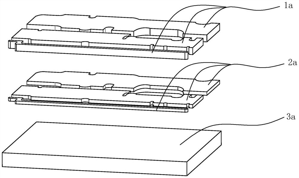
[0027] Specific Example 1: Such as figure 1 As well as figure 2 As well as image 3 Show, a method of making a high -guide hot -covered copper ceramic substrate, which includes the following steps:

First, the copper sheet of the substrate is stamped and molded, which is made of a copper sheet 1A required by the high -guided thermal covering copper ceramic substrate;

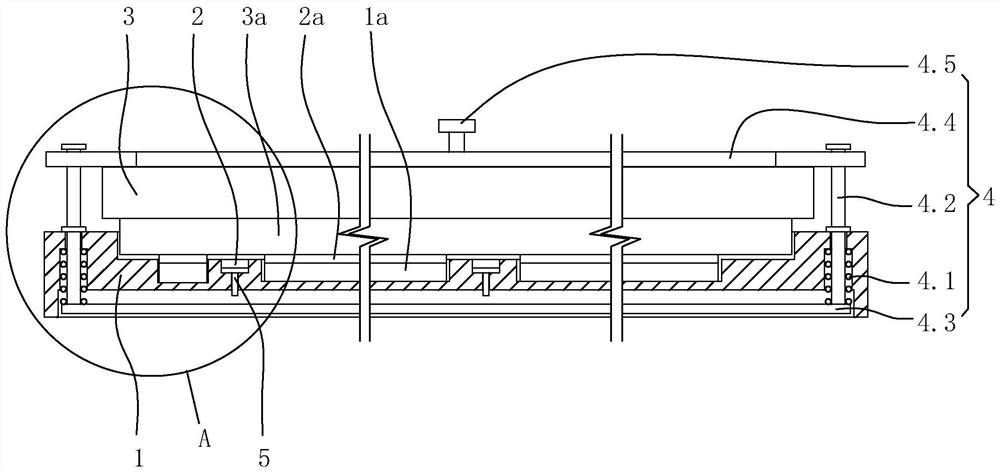
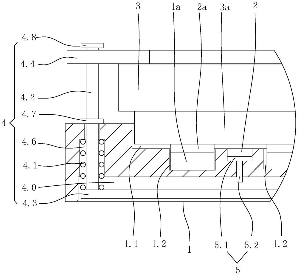
[0028] Second, positioning the copper sheet and the substrate welding sheet to the substrate welding workpiece. Specifically, the substrate welded installation of the substrate includes the bottom plate 1. The upper pressure plate 3. The ceramic board limited tank on the surface of the bottom plate 1.1 and several settings are set on several settings. The copper sheet limited tank 1.2 on the bottom surface of the ceramic board 1.2. The bottom surface of the ceramic board limited tank between the two copper sheets restricted tanks is equipped with a pre -installed tank 2 on the bottom surface of the ceramic board, and...


PUM


Abstract

The invention discloses a manufacturing method of a high-thermal-conductivity copper-clad ceramic substrate, and aims to provide the manufacturing method of the high-thermal-conductivity copper-clad ceramic substrate which is simple in manufacturing process, capable of reducing the manufacturing cost, firm in structural connection of the high-thermal-conductivity copper-clad ceramic substrate and free of the environmental protection problem of electroplating. The method sequentially comprises the following steps of: 1, carrying out punch forming on a substrate copper sheet and a substrate soldering lug; secondly, a substrate copper sheet and a substrate soldering lug are positioned on a substrate welding tool, the substrate welding tool comprises a bottom plate, an upper pressing plate, a ceramic plate limiting groove and a plurality of copper sheet limiting grooves, the ceramic plate limiting groove and the copper sheet limiting grooves are formed in the bottom plate, the substrate copper sheet is positioned in the copper sheet limiting grooves, and the substrate soldering lug is placed on the upper surface of the substrate copper sheet; thirdly, the solder resist preassembling groove is coated with solder resist; fourthly, the ceramic plate is placed in the ceramic plate limiting groove; fifthly, the ceramic plate limited in the ceramic plate limiting groove is pressed through an upper pressing plate; and sixthly, the base plate welding tool is placed in a vacuum brazing furnace for welding.

Description

Technical field [0001] The invention involves a method of making a ceramic substrate, which specifically involves a method of making a high -warming copper ceramic substrate. Background technique [0002] The existing high -guide thermal covering copper ceramic substrate production method is generally used to place a layer of metal membrane on the ceramic plate (taking copper as an example). At present, the production methods of this high -guide thermal covering copper ceramic substrate are mainly in shortcomings. First, the connection between copper and non -metallic (ceramic plate) is not reliable, and the performance of tensile or shear force is poor. Second, the surface coating technology Nowadays, there are electroplating and environmental protection problems. Invention content [0003] The purpose of the present invention is to provide a high -guide thermal covering copper ceramic substrate production method with high -guide and environmental protection issues that not onl...

Claims


Application Information

Patent Timeline
Patent Type & Authority Applications(China)
IPC IPC(8): B23K1/00B23K1/008B23K1/20B23K3/08
CPCB23K1/008B23K1/203B23K1/0008B23K3/087B23K2103/52Y02E60/10
Inventor 曾茂进夏波涛
Owner 祥博传热科技股份有限公司
Why Eureka
Try Eureka