Power distribution cabinet safety monitoring system
A technology of safety monitoring system and power distribution cabinet, which is applied in the direction of substation/power distribution device shell, electrical components, circuit devices, etc., can solve the problem of limited temperature adjustment ability of power distribution cabinet, and achieve the effect of ensuring cooling effect
- Summary
- Abstract
- Description
- Claims
- Application Information
AI Technical Summary
Problems solved by technology
Method used
Image
Examples
Embodiment 1
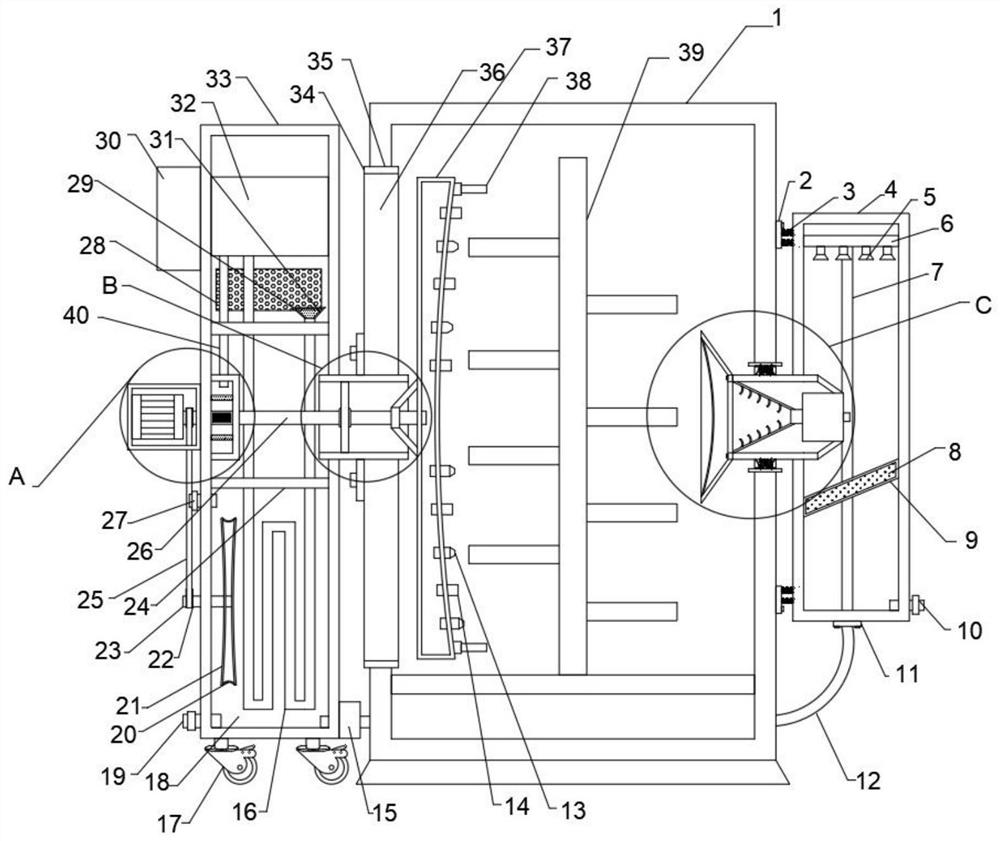
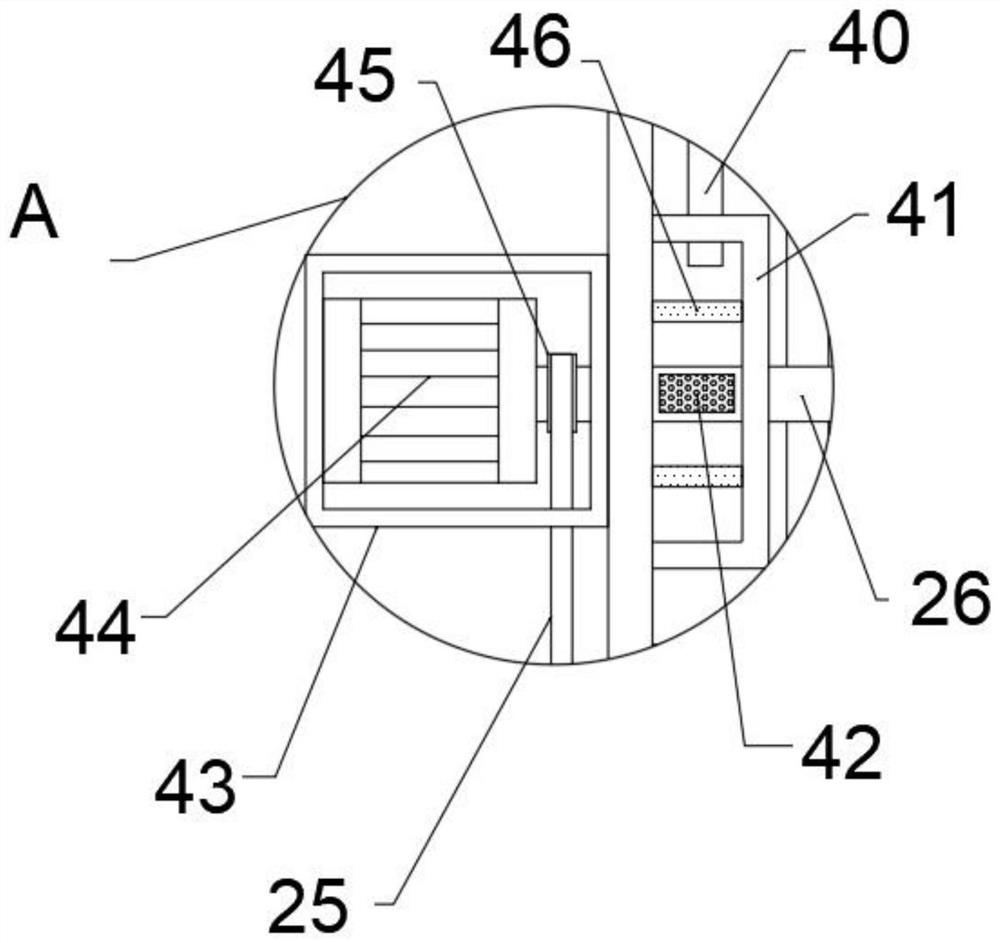
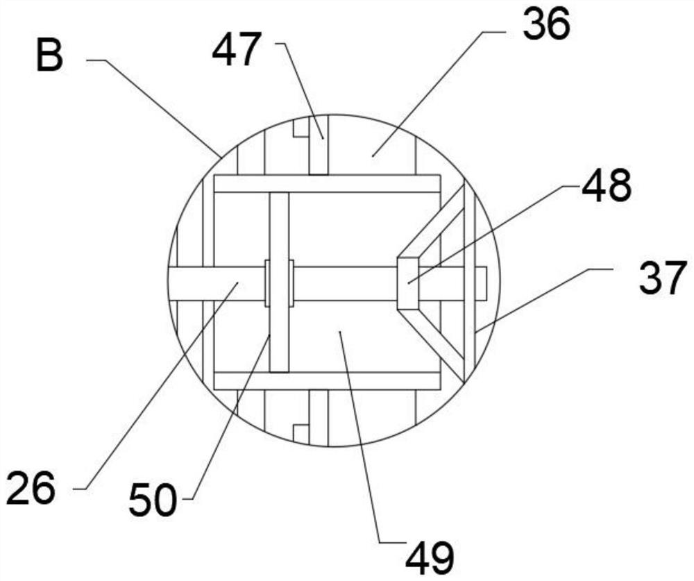
[0031] refer to Figure 1-6, a power distribution cabinet safety monitoring system, comprising a cabinet body 1, an equipment rack 39 is fixedly connected to the inner wall of the cabinet body 1, a slot 35 is opened on the outer wall of one end of the cabinet body 1, a connecting mechanism is arranged on the inner wall of the slot 35, and one end of the connecting mechanism is arranged There is an air outlet cooling mechanism, the outlet cooling mechanism is located at one end of the cabinet body 1, the other end of the connecting mechanism is provided with a side box 33, the outer wall of the side box 33 is fixedly connected with an electric control box 30, and the four corners of the bottom outer wall of the side box 33 are fixedly connected with pulleys 17 , the inner wall of the side box 33 is provided with an air supply mechanism, the inner wall of the side box 33 is fixedly connected with a partition 24, the bottom of the partition 24 is provided with a heat exchange mech...
Embodiment 2
[0041] refer to Figure 7 , a power distribution cabinet safety monitoring system, one end of the discharge pipe 56 is provided with a spoiler 61, the spoiler 61 is set in an arc shape, the outer wall of one end of the spoiler 61 is fixedly connected with a connecting block 62, and the other end of the connecting block 62 rotates Be connected with support bar 64, support bar 64 and process box 4 inwalls are rotationally connected, spoiler 61 end outer wall top and bottom all are fixedly connected with the 3rd spring 63, the 3rd spring 63 and process box 4 inwalls are fixedly connected.
[0042] During use, the air flow can be disturbed by setting the spoiler 61 which is rotatably connected by the support rod 64 and the connecting block 62 in the treatment box 4, so that the dust entering the treatment box 4 enters the treatment box 4 and moves upward. Improve the combination efficiency of the gas and liquid ejected from the atomizing nozzle 5, and connect the third spring 63 b...
Embodiment 3
[0044] refer to Figure 8 , a safety monitoring system for a power distribution cabinet, one end of the inner wall of the cabinet body 1 is fixedly connected with a collecting box 67, the inner wall of the collecting box 67 is provided with a second desiccant 65, and one end of the outer wall of the collecting box 67 is fixedly connected with an elastic closing plate 68, The outer wall of the elastic closing plate 68 is provided with a plurality of air holes, and one end of the elastic closing plate 68 is provided with a plurality of protrusions 66, the protrusions 66 and the elastic closing plate 68 are in natural contact, and the protrusions 66 are fixedly connected with the outer wall of the rotating box 37.
[0045] During use, by arranging a plurality of projections 66 on the outer wall of the rotating box 37, when the rotating box 37 rotates, the outer wall of the collecting box 67 on the inner wall of the cabinet body 1 is squeezed and rubbed, and the elastic closure of ...
PUM
 Abstract
Description
Claims
Application Information
 - R&D
- Intellectual Property
- Life Sciences
- Materials
- Tech Scout
- Unparalleled Data Quality
- Higher Quality Content
- 60% Fewer Hallucinations
Browse by: Latest US Patents, China's latest patents, Technical Efficacy Thesaurus, Application Domain, Technology Topic, Popular Technical Reports.
© 2025 PatSnap. All rights reserved.Legal|Privacy policy|Modern Slavery Act Transparency Statement|Sitemap|About US| Contact US: help@patsnap.com


