Processing equipment for composite fiber material capable of enhancing density

A composite fiber and processing equipment technology, applied in the cutting of textile materials, mechanical cleaning, textiles and papermaking, etc., can solve the problems of reducing the density of graphite felt, unable to drive graphite, polluting the environment, etc., and achieve the effect of increasing the density

Active Publication Date: 2022-05-31
JIA XIANG HONG RUN CARBON CO LTD
View PDF6 Cites 1 Cited by
  • Summary
  • Abstract
  • Description
  • Claims
  • Application Information

AI Technical Summary

Problems solved by technology

[0002] In the prior art, the needling machine has the following problems when needling graphite felt: due to the high-speed movement of the needles of the needling machine, the air pressure on the surface of the graphite felt is too high, and the fibers on the upper surface of the graphite felt take off, and the fibers will fall. In the surroundings, polluting the surrounding environment, when the high-speed moving needles are rising on the graphite felt, the needle-punched hooks will take the fibers that have not been displaced out of the graphite felt, which will destroy the fiber layer on the upper surface of the graphite felt, resulting in graphite felt The density decreases, the strength decreases, and the current needle loom drives the graphite felt to move left or right, and cannot drive the graphite to move back and forth, so that the position where the needle loom brings the fiber into the graphite felt is limited.

Method used


Image

  • Processing equipment for composite fiber material capable of enhancing density
  • Processing equipment for composite fiber material capable of enhancing density
  • Processing equipment for composite fiber material capable of enhancing density

Examples


Embodiment 1

[0040] A processing equipment for composite fiber materials that can increase density, such as Figure 1-14 As shown, it includes a chassis 1, a conveying system 2, a needle punching system 3, a stretching system 4 and a fiber removal system 5; the left part of the upper surface of the chassis 1 and the right part of the upper surface are connected with the conveying system 2; The middle part of the surface is connected with an acupuncture system 3; the acupuncture system 3 is connected with a stretching system 4; the acupuncture system 3 is connected with a fiber removal system 5;

[0041] When in use, first place the processing equipment for the composite fiber material that can enhance the density at the required position, and place the bottom frame 1 on a stable position. First, the operator places a roll of graphite felt on the right side of the conveying system 2, Then pull the graphite felt out, pass through the acupuncture system 3, the stretching system 4 and the fibe...

Embodiment 2

[0043] On the basis of Example 1, such as Figure 1-14 As shown, the conveying system 2 includes a first conveying frame 201, a second conveying frame 202, a third conveying frame 203 and a fourth conveying frame 204; 1 The right part of the upper surface is fixedly connected with the second conveying frame 202, and the second conveying frame 202 is located on the left side of the first conveying frame 201; A fourth transport frame 204 is fixedly connected to the left part, and the fourth transport frame 204 is located on the left of the third transport frame 203 .

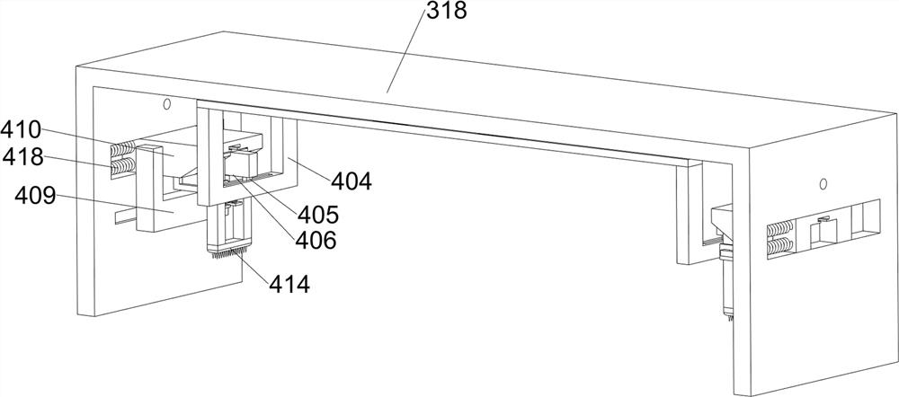
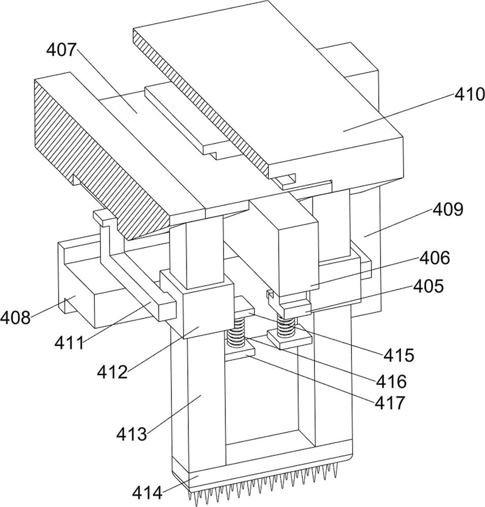
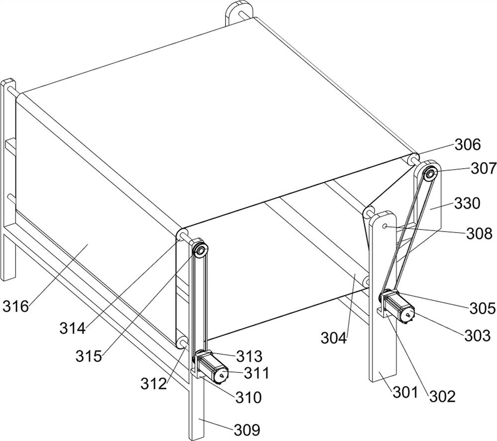
[0044] The acupuncture system 3 includes a fifth support frame 301, a first mounting bracket 302, a first motor 303, a first transmission roller 304, a first transmission wheel 305, a second transmission roller 306, a second transmission wheel 307, a third transmission Roller 308, sixth support frame 309, second mounting bracket 310, second motor 311, fourth transmission roller 312, third transmission wheel 313, ...

Embodiment 3

[0059] On the basis of Example 2, such as Figure 15 As shown, a cutting system 6 is also included; the left part of the upper surface of the bottom frame 1 is connected with a cutting system 6; the cutting system 6 includes a fifth conveying frame 601, a circular cutter 602 and a third collection box 603; The fifth conveyor frame 601 is fixedly connected to the left part of the surface, and the fifth conveyor frame 601 is located between the third conveyor frame 203 and the fourth conveyor frame 204; the front part and the rear part of the fifth conveyor frame 601 are respectively fixed with a conveyor roller. Circular cutter 602 ; two third collection boxes 603 are affixed to the upper left part of the bottom frame 1 , and the two third collection boxes 603 are located on the left of the fifth conveying frame 601 .

[0060] When the graphite felt slowly moves to the left, the conveying roller of the fifth conveying frame 601 is controlled to rotate, and the conveying roller ...


PUM


Abstract

The invention relates to the field of graphite felt manufacturing, in particular to processing equipment for a composite fiber material capable of enhancing density. The invention aims to solve the technical problems that when the needling machine runs at a high speed, fibers on the upper surface of a graphite felt can be driven to take off, and fibers in the graphite felt can be brought out. According to the technical scheme, the processing equipment for the composite fiber material capable of enhancing the density comprises a bottom frame, a conveying system, a needling system and the like; the left part and the right part of the upper surface of the underframe are connected with a conveying system; the middle of the upper surface of the underframe is connected with a needling system. The conveying system is designed, continuous leftward conveying of the graphite felt is achieved, and the needling system can conveniently enhance the density of the graphite felt; a needling system is designed, vertical fibers on the upper surface of the graphite felt are smoothed, meanwhile, the graphite felt is punctured repeatedly, the fibers on the upper surface of the graphite felt are brought into the graphite felt, friction force between the fibers in the graphite felt is increased, the strength of the graphite felt is improved, and the density of the graphite felt is increased.

Description

technical field [0001] The invention relates to the field of graphite felt production, in particular to processing equipment for a composite fiber material capable of increasing density. Background technique [0002] In the prior art, the needling machine has the following problems when needling graphite felt: due to the high-speed movement of the needles of the needling machine, the air pressure on the surface of the graphite felt is too high, and the fibers on the upper surface of the graphite felt take off, and the fibers will fall. In the surroundings, polluting the surrounding environment, when the high-speed moving needles are rising on the graphite felt, the needle-punched hooks will take the fibers that have not been displaced out of the graphite felt, which will destroy the fiber layer on the upper surface of the graphite felt, resulting in graphite felt The density decreases, the strength decreases, and the current needle loom drives the graphite felt to move left ...

Claims


Application Information

Patent Timeline
Patent Type & Authority Applications(China)
IPC IPC(8): D04H18/02D06G1/00D06H7/00
CPCD04H18/02D06G1/00D06H7/00
Inventor 刘湘鹏
Owner JIA XIANG HONG RUN CARBON CO LTD
Why Eureka
Try Eureka