
Electric auxiliary paper collecting device for automatic die-cutting machine

A die-cutting machine and auxiliary delivery technology, which is used in transportation and packaging, thin material handling, and sending objects, etc., can solve the problems of scratched printed matter, reduced delivery quality, and uneven delivery, and achieves improved service life. The effect of improving delivery quality and improving stability

Pending Publication Date: 2022-05-31
唐山恒峰机械制造有限公司
View PDF0 Cites 1 Cited by
  • Summary
  • Abstract
  • Description
  • Claims
  • Application Information

AI Technical Summary

Problems solved by technology

[0003] However, the electric sub-delivery device of the existing automatic die-cutting machine mainly adopts the structure that the chain drives the belt to run forward and backward. Due to the lack of a limit structure during the operation of this structure, it is easy for the device to move the bottom of the paper stack during use. The paper messes up and scratches the printed matter, and the paper delivery is not neat, which greatly reduces the quality of the paper delivery during the use of the device. Secondly, the motor drive sprocket on the electric secondary delivery device of the existing automatic die-cutting machine mainly uses The sprocket wheel with ordinary structure will continue to work when the paper delivery capacity on the device exceeds the rated load, which will easily damage the device and greatly reduce the service life of the paper delivery device

Method used


Image

  • Electric auxiliary paper collecting device for automatic die-cutting machine
  • Electric auxiliary paper collecting device for automatic die-cutting machine
  • Electric auxiliary paper collecting device for automatic die-cutting machine

Examples


Embodiment Construction

[0035] The present invention will be further described below in conjunction with accompanying drawing:

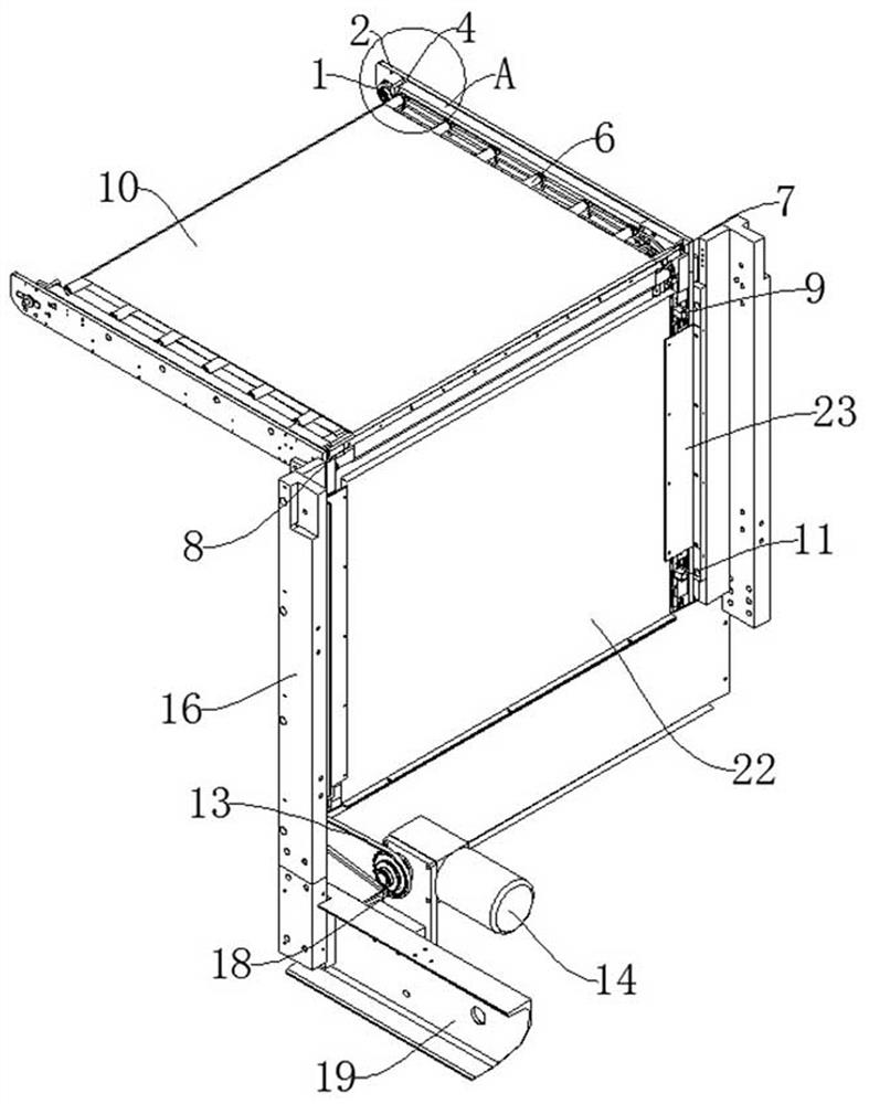
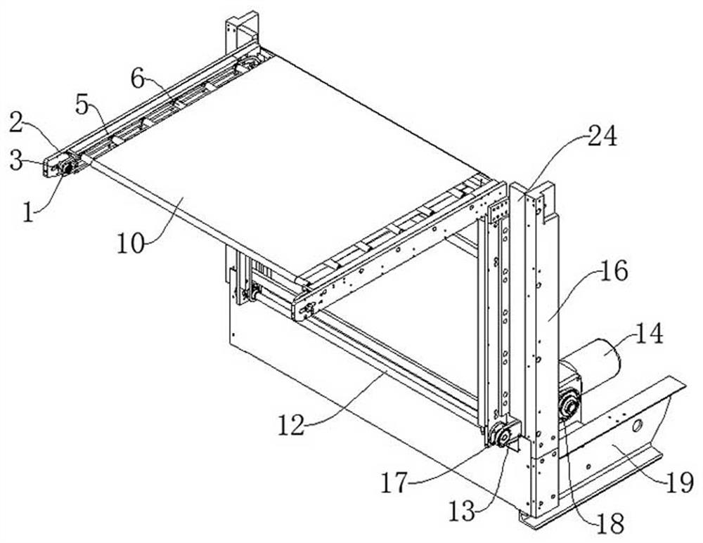
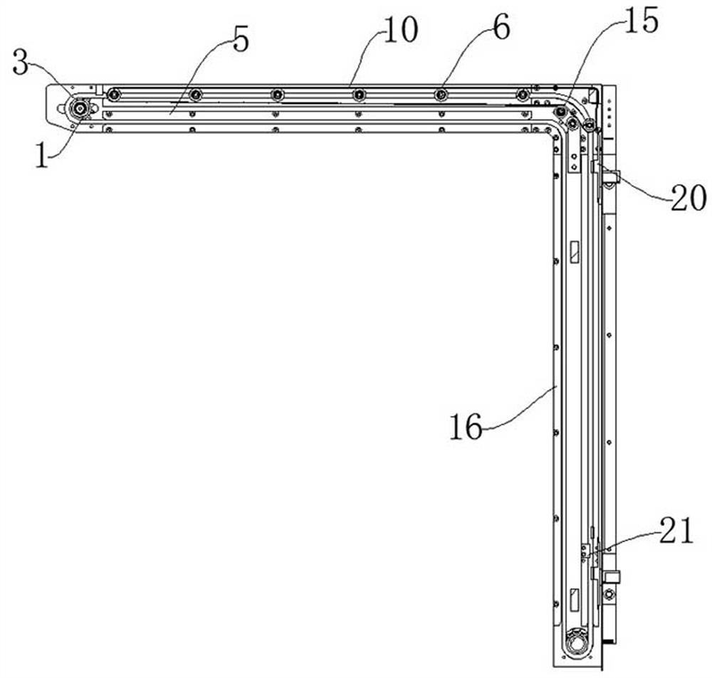
[0036] Such as Figure 1-Figure 4As shown, an electric auxiliary delivery device for an automatic die-cutting machine includes a support plate 2, a vertical plate 16, a chain guide rail 5 and an upper limit switch 9, and the vertical plate 16 is provided on one side of the support plate 2 , the support plate 2 and the vertical plate 16 all have two, the chain guide rail 5 is installed on the support plate 2 and the vertical plate 16, and the chain guide rail 5 is located on the support plate 2 An upper limit block 4 is installed at one end, and a lower limit block 21 is installed at the other end of the chain guide rail 5 on the vertical plate 16, and the upper limit block 4 and the lower limit block 21 can be used when the belt 10 is abnormal When working, the stable use of the device is ensured by resisting the paper support roller 6. The support roller transmission chai...


PUM


Abstract

The invention discloses an electric auxiliary paper collecting device for an automatic die-cutting machine. The paper collecting device has the beneficial effects that by arranging a chain guide rail, an upper limiting switch, a lower limiting switch, an upper limiting block, a lower limiting block, a belt fixing clamping plate and a belt fixing plate, when the paper collecting device is used, on one hand, the vertical movement position of a belt in the normal transmission process can be effectively limited under the action of the upper limiting switch and the lower limiting switch; on the other hand, when an upper limiting switch and a lower limiting switch are out of order, effective limiting of the belt in the lifting process can be achieved under the abutting action of an upper limiting block and a lower limiting block and a paper supporting roller, the stability of the device in the using process is greatly improved, and meanwhile through mutual cooperation of a belt fixing clamping plate and a belt fixing plate, the device is convenient to use. The belt can be effectively clamped and fixed when moving relative to the paper supporting roller, and therefore the defects that in the using process of the device, paper on the lowermost portion of a paper pile is disordered, printed matter is scratched, and paper collection is not tidy are effectively overcome.

Description

technical field [0001] The invention relates to the technical field of automatic die-cutting machines, in particular to an electric auxiliary delivery device for automatic die-cutting machines. Background technique [0002] Automatic die-cutting machine is also called beer machine, cutting machine, CNC stamping machine, mainly used for die-cutting of some corresponding non-metallic materials, self-adhesive, EVA, double-sided adhesive, electronics, mobile phone rubber pad, etc. (full cut, half-broken), indentation and bronzing operations, lamination, automatic waste discharge, the die-cutting machine uses steel knives, metal molds, steel wires (or templates carved from steel plates), and applies a certain pressure through the embossing plate to print the printed matter Or cardboard rolled and cut into a certain shape. It is an important equipment for post-press packaging processing and molding, among which electric secondary delivery devices are often used on automatic die-c...

Claims


Application Information

Patent Timeline
Patent Type & Authority Applications(China)
IPC IPC(8): B65H29/18B65H29/52
CPCB65H29/18B65H29/52B65H2701/1131Y02P70/10
Inventor 周永辉徐庆国
Owner 唐山恒峰机械制造有限公司
Learn More