Pressing device applied to multi-specification activated carbon
An activated carbon, multi-specification technology, applied in the field of activated carbon molding equipment, can solve the problems of flexible change of finished product shape, single equipment function, low work efficiency, etc., to achieve the effect of reducing manpower, liberating labor, and improving functions
- Summary
- Abstract
- Description
- Claims
- Application Information
AI Technical Summary
Problems solved by technology
Method used
Image
Examples
Embodiment 1
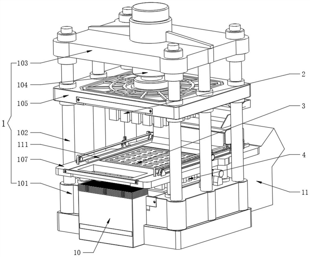
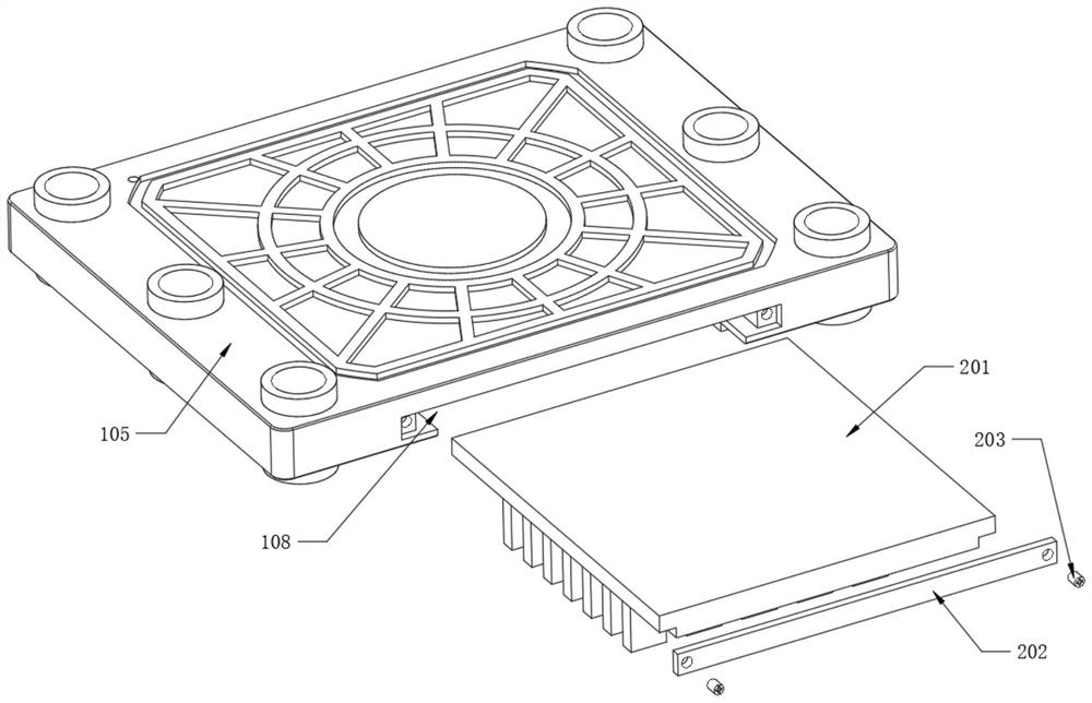
[0047] Refer to attached image 3 , the inner lower end of the pressing plate 105 is fixedly provided with an installation groove 108, and the inside of the pressing plate 105 is assembled with a pressing material structure 2 through the installation groove 108. The pressing material structure 2 also includes a pressing material plate 201, and the pressing material plate 201 is slidably assembled in the installation groove inside of a 108, and one end of the binder plate 201 is provided with a fixed plate 202, and the fixed plate 202 is fixedly connected with the pressure plate 105 through the fixing screw 203 screwed at both ends, and the fixed plate 202 can be removed to make the binder plate 201 is separated from the platen 105 .
[0048] Refer to attached Figure 4 , the interior of the auxiliary plate 107 is fixedly provided with the second installation groove 109, and the inside of the auxiliary plate 107 is movably assembled with a mold structure 3 through the second i...
Embodiment 2
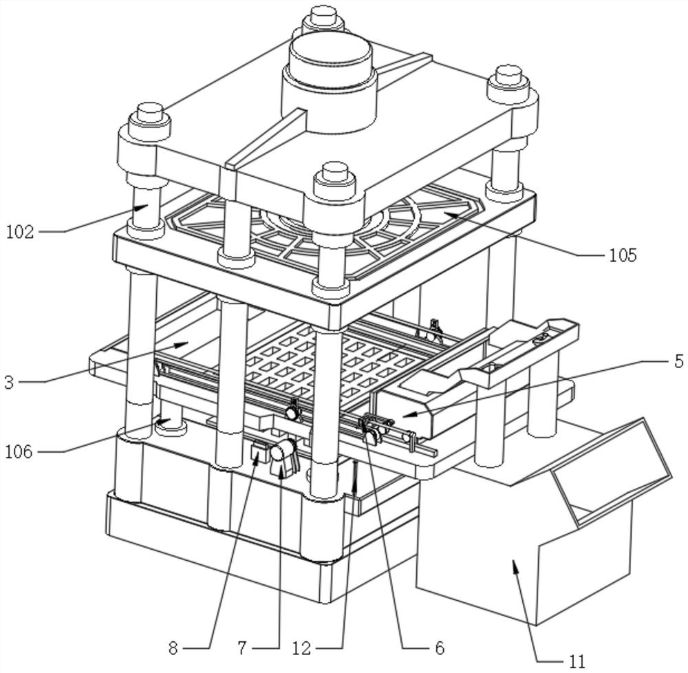
[0053] Refer to attached Figure 8 The feeding structure 5 also includes a feeding shell 501, the lower surface of the feeding shell 501 is fixedly provided with a discharge port 502, the two ends of the feeding shell 501 are fixedly equipped with a moving motor, and the output end of the moving motor is fixedly installed with a The power wheel 503, and the power wheel 503 is combined with the wheel rail 111, the lower surface of the feeding shell 501 is fixedly provided with a strip brush 504, and the outer walls of both sides of the feeding shell 501 are rotatably connected with a joint rod 505, the joint rod The outer wall of 505 is fixedly provided with abutment rod 506, and the upper surface of bottom support 101 is located directly below the abutment rod 506 and is fixedly provided with separation rod 12, and the mobile motors inside both ends of feeding shell 501 are all started, and the corresponding power wheels 503 will rotate, and then drive the feeding shell 501 to...
Embodiment 3
[0056] Refer to attached Figure 6 , the conveying mechanism 6 also includes a conveying plate 601, and both sides of the conveying plate 601 are fixedly provided with side rods 602, and one end of the movable connecting rod 505 is movably clamped with the side rods 602, and then the replenishing shell 501 is used to move to complete feeding During the work, at this time, the movable connecting rod 505 is clamped with the side rod 602, and the feeding shell 501 can drive the feeding plate 601 to move back and forth, and both sides of the upper surface of the auxiliary plate 107 are fixedly equipped with guide rods 603, two A sliding connection is formed between the side rod 602 and the two guide rods 603. The upper surface of the auxiliary plate 107 is symmetrically fixed on both sides with a wheel frame 604, and the surface of the wheel frame 604 is provided with a chain 605. The two side rods 602 and two The chains 605 form a fixed connection. Due to the fixed connection bet...
PUM
 Abstract
Description
Claims
Application Information
 - R&D
- Intellectual Property
- Life Sciences
- Materials
- Tech Scout
- Unparalleled Data Quality
- Higher Quality Content
- 60% Fewer Hallucinations
Browse by: Latest US Patents, China's latest patents, Technical Efficacy Thesaurus, Application Domain, Technology Topic, Popular Technical Reports.
© 2025 PatSnap. All rights reserved.Legal|Privacy policy|Modern Slavery Act Transparency Statement|Sitemap|About US| Contact US: help@patsnap.com


