
Aero-optical thermal radiation effect correction method, device, equipment and storage medium

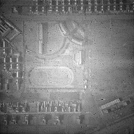
A technology of aero-optics and thermal radiation, which is used in image enhancement, image analysis, instruments, etc. It can solve the problems of inaccurate correction of thermal radiation degradation images, and achieve the effect of uniform surface distribution and clear corrected images.

Active Publication Date: 2022-07-26
WUHAN INSTITUTE OF TECHNOLOGY
View PDF8 Cites 0 Cited by
  • Summary
  • Abstract
  • Description
  • Claims
  • Application Information

AI Technical Summary

Problems solved by technology

The correction of the aero-optical thermal radiation degradation image in the prior art is not accurate enough, so a new correction method is needed to make the corrected image clearer

Method used


Image

  • Aero-optical thermal radiation effect correction method, device, equipment and storage medium
  • Aero-optical thermal radiation effect correction method, device, equipment and storage medium
  • Aero-optical thermal radiation effect correction method, device, equipment and storage medium

Examples


Embodiment Construction

[0054] The preferred embodiments of the present invention are specifically described below with reference to the accompanying drawings, wherein the accompanying drawings constitute a part of the present invention, and together with the embodiments of the present invention, are used to explain the principles of the present invention, but not to limit the scope of the present invention.

[0055]In the description of the present invention, "plurality" means two or more, unless otherwise expressly and specifically defined. Reference herein to an "embodiment" means that a particular feature, structure, or characteristic described in connection with the embodiment can be included in at least one embodiment of the present invention. The appearances of the phrase in various places in the specification are not necessarily all referring to the same embodiment, nor a separate or alternative embodiment that is mutually exclusive of other embodiments. It is explicitly and implicitly unders...


PUM


Abstract

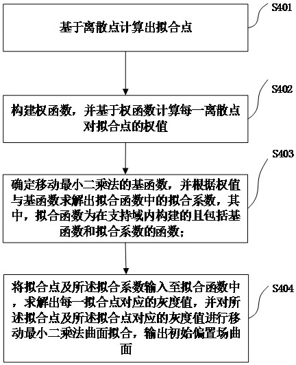
The invention relates to an aero-optical thermal radiation effect correction method, device, equipment and storage medium. The method includes: acquiring aero-optical thermal radiation degradation images, filtering the degraded images to obtain the filtered images; performing down-sampling processing on the filtered images And generate discrete points; use the moving least squares-based surface fitting method to fit the discrete points to the initial bias field surface; input the initial bias field surface into the pre-established degradation model, and use the alternate iterative minimum method to output to meet the preset Corrected image and bias field for iterative conditions. The corrected image output in the present invention is clearer, and the correction effect is improved.

Description

technical field [0001] The present invention relates to the technical field of image correction, in particular to a method, device, equipment and storage medium for correcting aero-optical thermal radiation effects. Background technique [0002] When an aircraft carrying an optical imaging system flies at high speed in the atmosphere, there will be a violent interaction between its optical hood and the atmosphere, and a severe aero-optical thermal radiation effect will be produced at the optical side windows of the aircraft. The image produced by the optical imaging system under the effect of aero-optical thermal radiation is very blurred. The heat generated by the air compression causes the electronic response characteristics of the imaging focal plane to change, resulting in nonlinear saturation of the image and serious distortion. [0003] Aero-optics thermal radiation effect correction method is an important link in the study of aero-optics thermal radiation effect corre...

Claims


Application Information

Patent Timeline
Patent Type & Authority Patents(China)
IPC IPC(8): G06T5/00G06T7/90
CPCG06T7/90G06T5/70Y02T90/00
Inventor 洪汉玉鲁浩渊时愈张丽琴杜敦伟赵欣张天序桑农冯先成钟卫军
Owner WUHAN INSTITUTE OF TECHNOLOGY
Learn More