
Method for multi-software joint simulation and design of hot-pressing light guide plate lattice points and application thereof

A light guide plate network point and co-simulation technology, applied in the field of backlight, can solve problems such as reducing research and development time, achieve the effects of shortening the development cycle, accurate results, and reducing development costs

Pending Publication Date: 2022-05-20
青岛国骐光电科技有限公司
View PDF0 Cites 0 Cited by
  • Summary
  • Abstract
  • Description
  • Claims
  • Application Information

AI Technical Summary

Problems solved by technology

The present invention provides a multi-software joint simulation and method for designing hot-pressed light guide plate outlets. By making complex modeling of regular outlets and using multiple software joint modeling methods, a method that can be directly used for simulation design of light guide plates is constructed. The network model solves the problem of optimizing the design of the light guide plate by relying on multiple processing experiments in the past, which greatly reduces the research and development time and saves the production cost.

Method used


Image

  • Method for multi-software joint simulation and design of hot-pressing light guide plate lattice points and application thereof
  • Method for multi-software joint simulation and design of hot-pressing light guide plate lattice points and application thereof
  • Method for multi-software joint simulation and design of hot-pressing light guide plate lattice points and application thereof

Examples


Embodiment 1

[0037] The light guide plate used in this embodiment is a side-type 21.5-inch backlight, which is composed of a light source, a light guide plate, a reflection film, a diffusion film and a prism film. Among them, the size of the light guide plate is 478×278×2.0mm; the material is PMMA; the refractive index is 1.49; the light source is an LED light strip, which is arranged at equal intervals with 46 LEDs, the output angle is 120°, and the luminous flux of each LED is 22LM.

[0038] A method for multi-software co-simulation and design of dots of a heat-pressed light guide plate, comprising the following steps:

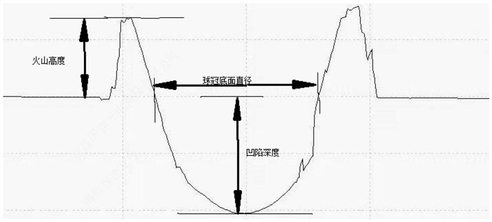
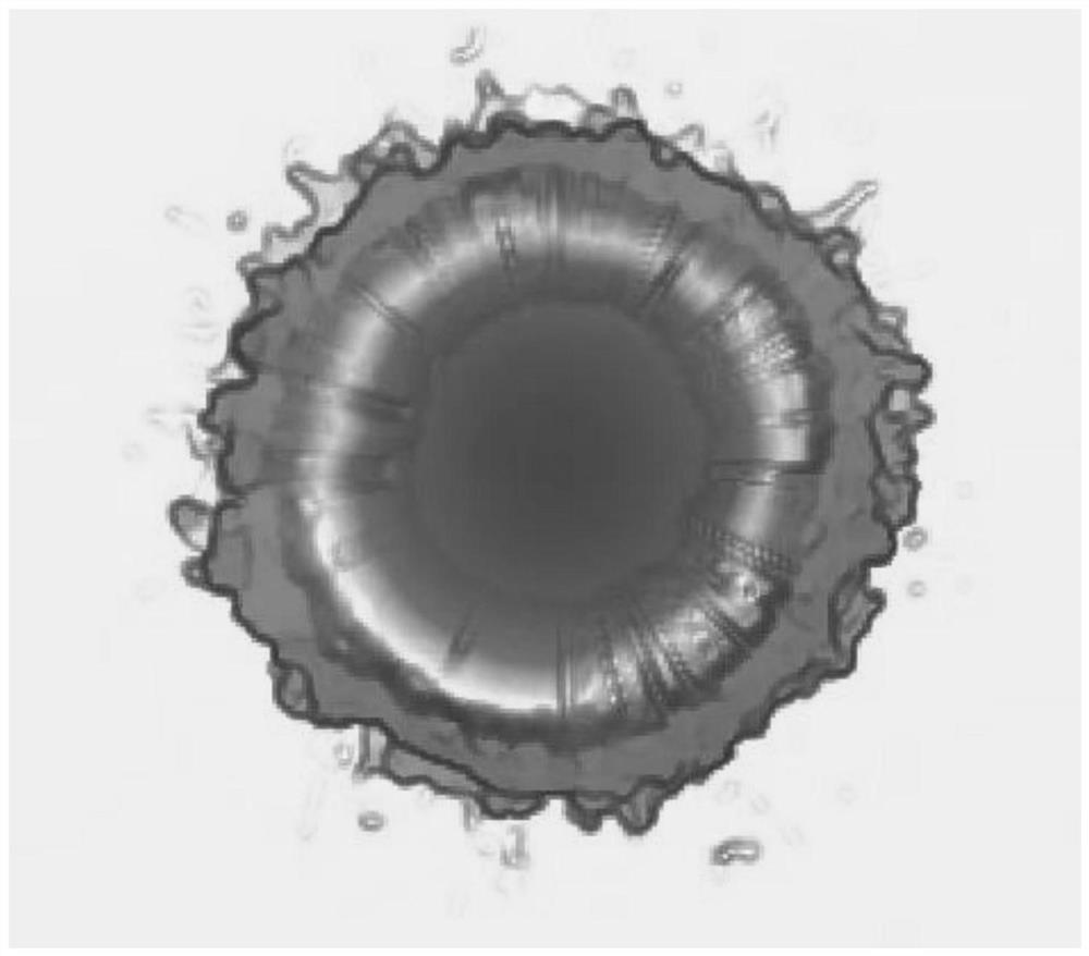
[0039] S1. Process the microstructure, use shooting software to measure the microstructure, and measure the parameters of the crater network;

[0040] S2. Adopt data processing software to process the crater outlet parameter measured in step S1;

[0041] S3. Use 3D software for 3D modeling, and perform Boolean cutting on the crater network parameters after smoothing and...

Embodiment 2

[0053] In addition, the present invention also provides the application of a multi-software co-simulation and method for designing hot-pressed light guide plate dots in the technical field of liquid crystal display and lighting.


PUM

PropertyMeasurementUnit
diameteraaaaaaaaaa
refractive indexaaaaaaaaaa

Abstract

The invention relates to a multi-software joint simulation and hot-pressing light guide plate dot design method, which comprises the following steps of S1, processing a microstructure, measuring the microstructure by adopting shooting software, and measuring volcanic vent dot parameters; s2, processing the volcanic vent network parameters by adopting data processing software; s3, carrying out three-dimensional modeling by adopting three-dimensional software, and carrying out Boolean cutting on the volcanic vent dot parameters after smooth denoising; s4, optical simulation design software is adopted to establish simulation analysis of volcanic vent dots, and a model is obtained; s5, designing the density grade of the light guide plate by adopting optical dot design software, and generating a dot diagram; and S6, establishing a dot diagram by adopting optical simulation design software, and carrying out analogue simulation analysis on the volcanic vent dot model to obtain a light guide plate dot model. According to the method for multi-software joint simulation and design of the hot-pressing light guide plate lattice points, the problem that in the prior art, the light guide plate can only be subjected to optimization design through multiple machining experiments is solved, the research and development time is greatly shortened, and the production cost is saved.

Description

technical field [0001] The invention relates to the field of backlight technology, in particular to a multi-software co-simulation and method for designing hot-pressed light guide plate dots and its application. Background technique [0002] As the most important module in the liquid crystal display backlight module, the light guide plate is responsible for the transmission of light in the backlight module. By changing the law of light transmission, the light is evenly emitted from the light-emitting surface of the light guide plate. Therefore, the light guide plate is a key factor determining the quality of the backlight module. The dot structure of the light guide plate will directly affect the uniformity and brightness of the backlight module, and different processing methods will also produce different dot structures. Due to the extremely complex structure of the diffuser dots of the heat-pressed light guide plate, it is difficult to directly carry out simulation design...

Claims


Application Information

Patent Timeline
Patent Type & Authority Applications(China)
IPC IPC(8): G02B27/00G02B6/00G02F1/13357F21V8/00
CPCG02B27/0012G02B6/0043G02B6/0065G02F1/1336F21V2200/20Y02E60/00
Inventor 王晓刘明辉张子宾
Owner 青岛国骐光电科技有限公司
Learn More