
A declaration warning system

A technology of warning system and warning lights, applied in the direction of anti-collision system, brake, arrangement of variable traffic indication, etc.

Inactive Publication Date: 2004-04-07
BAYERISCHE MOTOREN WERKE AG
View PDF0 Cites 0 Cited by
  • Summary
  • Abstract
  • Description
  • Claims
  • Application Information

AI Technical Summary

Problems solved by technology

However, this does not reduce or overcome the fundamental drawbacks of conventional brake lights described above

Method used

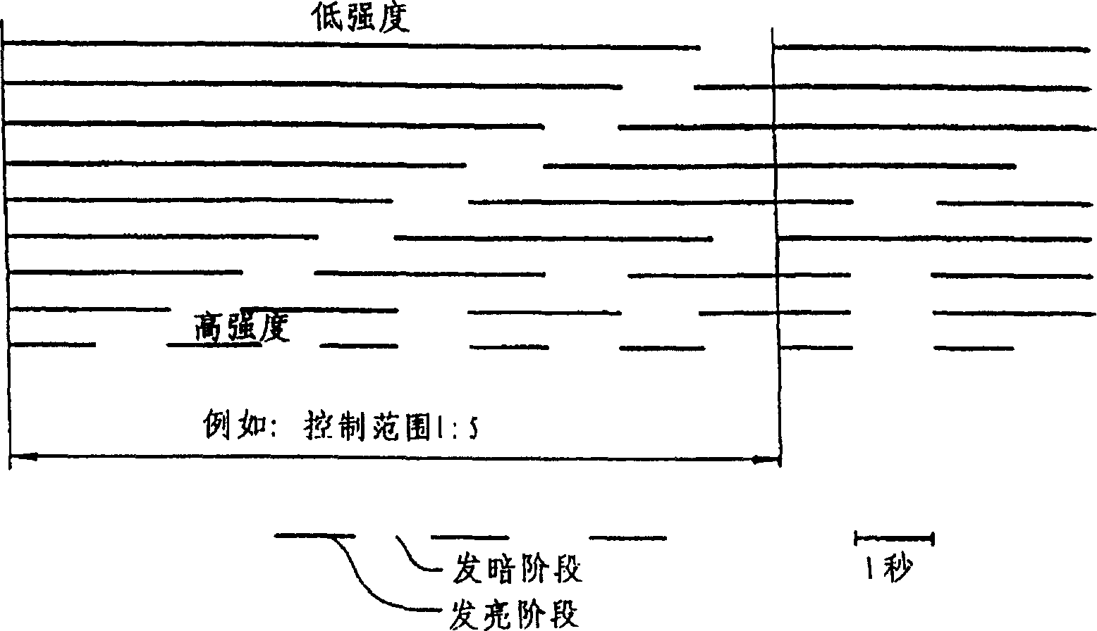
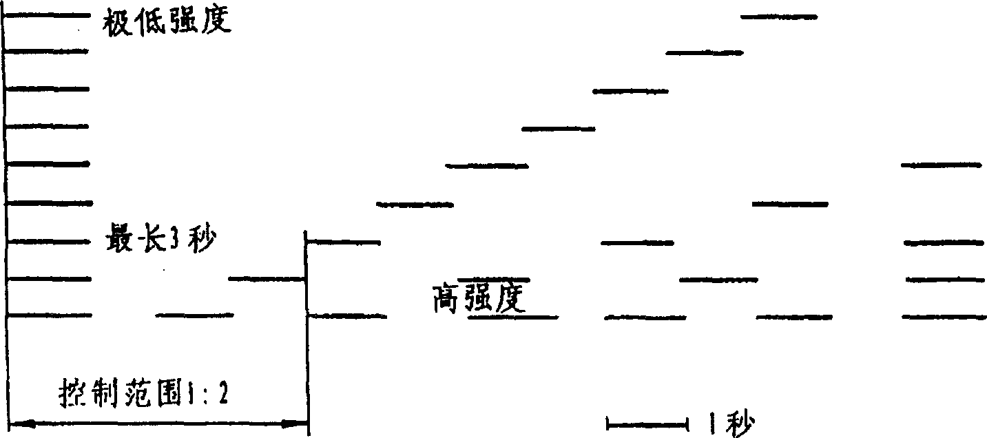
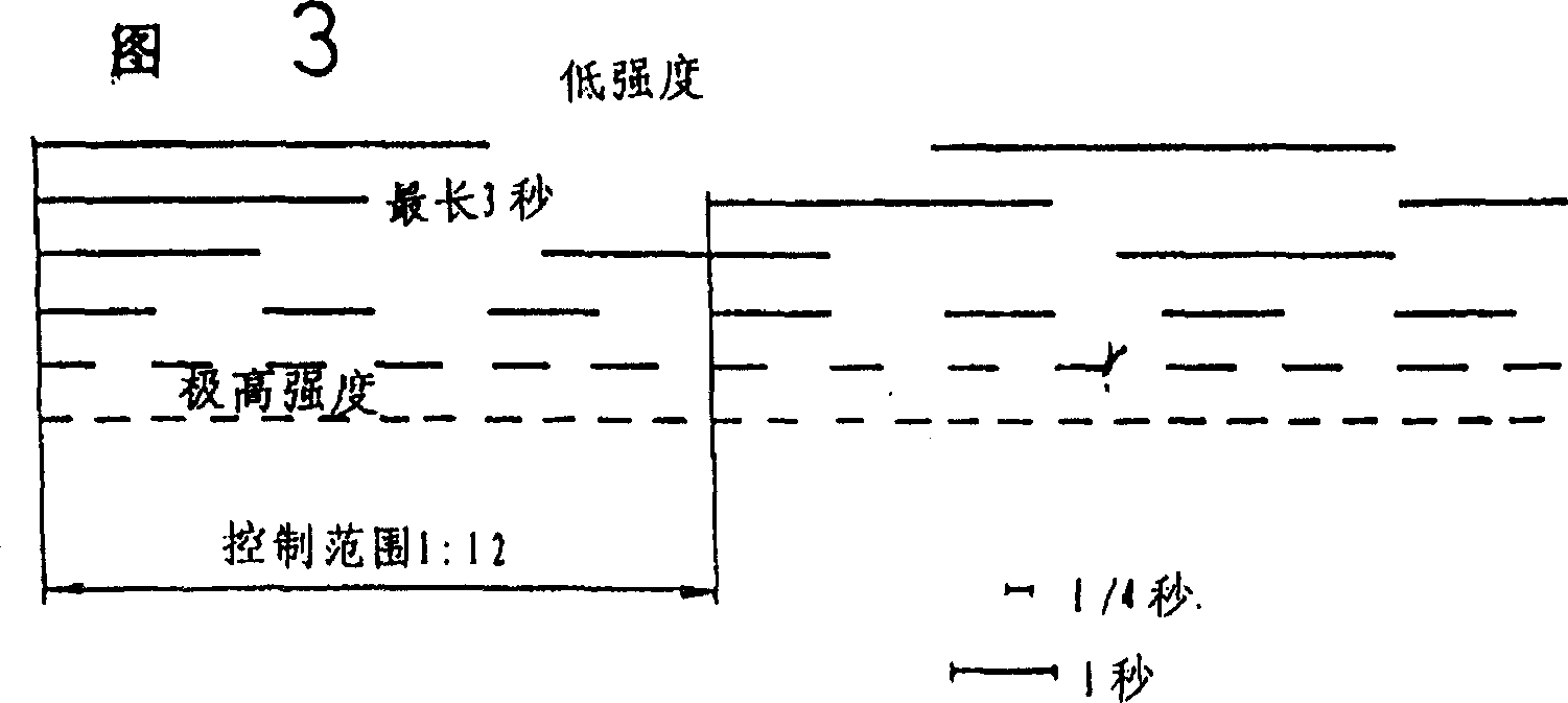

Image

  • A declaration warning system
  • A declaration warning system
  • A declaration warning system

Examples


example 1

[0036] Example 1: Two vehicles with speed V 0 = 50 km / h = 13.9 m / s; the distance left a = 1 2 v = 25 m; the first car hits a stationary obstacle; reaction time t = 1 second, maximum braking acceleration b = 8.7 m / s 2 (on dry road)

[0037]

[0038] Make full use of the maximum possible braking acceleration, and the remaining braking distance of 11.1 meters will be just enough to stop the vehicle behind from 50 km / h without rear-end collision.

example 2

[0039] Example 2: V 0 = 100 km / h = 27.8 m / s; a = 1 2 v = 50 m, t = 1 sec;

[0040] b=8.7 m / s 2

[0041]

[0042] This example has the same reaction time and braking acceleration as Example 1 and although the prescribed safety distance is also maintained, a rear-end collision will occur at a speed of 29 kilometers per hour.

[0043] [In the case of a series of separate deceleration events occurring in succession, e.g. with b A , b B , b C , which is naturally suitable to be represented by the sum of risk factors, for example: ∑∑G=∑G A +∑G B +∑G C ]

[0044] at V 0 with a value of 150 km / h, will collide at a speed of 63 km / h, at V 0 A value of 200 km / h will result in a collision at 100 km / h.

[0045] Therefore, in a particularly advantageous form of the warning flashing system according to the invention, the velocity V of the vehicle prior to the collision should be tak...


PUM


Abstract

A deceleration warning device and a method for its control serve to reduce the risk of rear-end collisions in road traffic or in other movement processes. In order to avoid or to reduce the disadvantages of conventional brake lights and flashing hazard warning systems, the intensity of warning given by the deceleration warning device of a vehicle travelling ahead is dependent on the size of the risk value G which originates from this vehicle and can be effective for subsequent vehicles.

Description

technical field [0001] The invention relates to a system and a control method thereof, by means of which the risk of rear-end collisions in road traffic can be reduced. Background technique [0002] Casualties and property damage caused by traffic accidents caused by rear-end collisions are very extensive. It should be admitted that in the last ten years great progress has been made in the in-depth development of passive protection against accidents, by means of which the consequences of accidents are reduced. Only crush zones, seat belts, seat head restraints and airbags need to be considered in this respect. [0003] However, the development of brake lights that emerged in the 1920s has hardly taken a significant step forward. The improvement of the brake light is only brighter and somewhat bigger, and the pattern that the brake light turns on when the brake pedal is pressed, even if the vehicle is not slowing down, has not changed. In the US, a center-mounted third bra...

Claims


Application Information

Patent Timeline
Patent Type & Authority Patents(China)
IPC IPC(8): B60R21/00B60Q1/30B60Q1/44B60Q1/50B60Q1/52B60T8/00B60T8/172B60T8/1763B60W30/00G08G1/09G08G1/16
CPCB60Q1/302B60Q1/444B60Q2300/41
Inventor 马克斯·杰哈赫
Owner BAYERISCHE MOTOREN WERKE AG
Learn More