Anti-falling safety device with automatic grease injection function for elevator
An anti-fall safety device and automatic technology, applied in the direction of automatic clutch, engine lubrication, clutch, etc., can solve the problems such as the centrifugal block easily triggering the braking effect, the failure of the tension spring, the weakening and other problems, so as to avoid the braking distance from being too long. , the effect of improving the heat dissipation capacity
- Summary
- Abstract
- Description
- Claims
- Application Information
AI Technical Summary
Problems solved by technology
Method used
Image
Examples
Embodiment 1
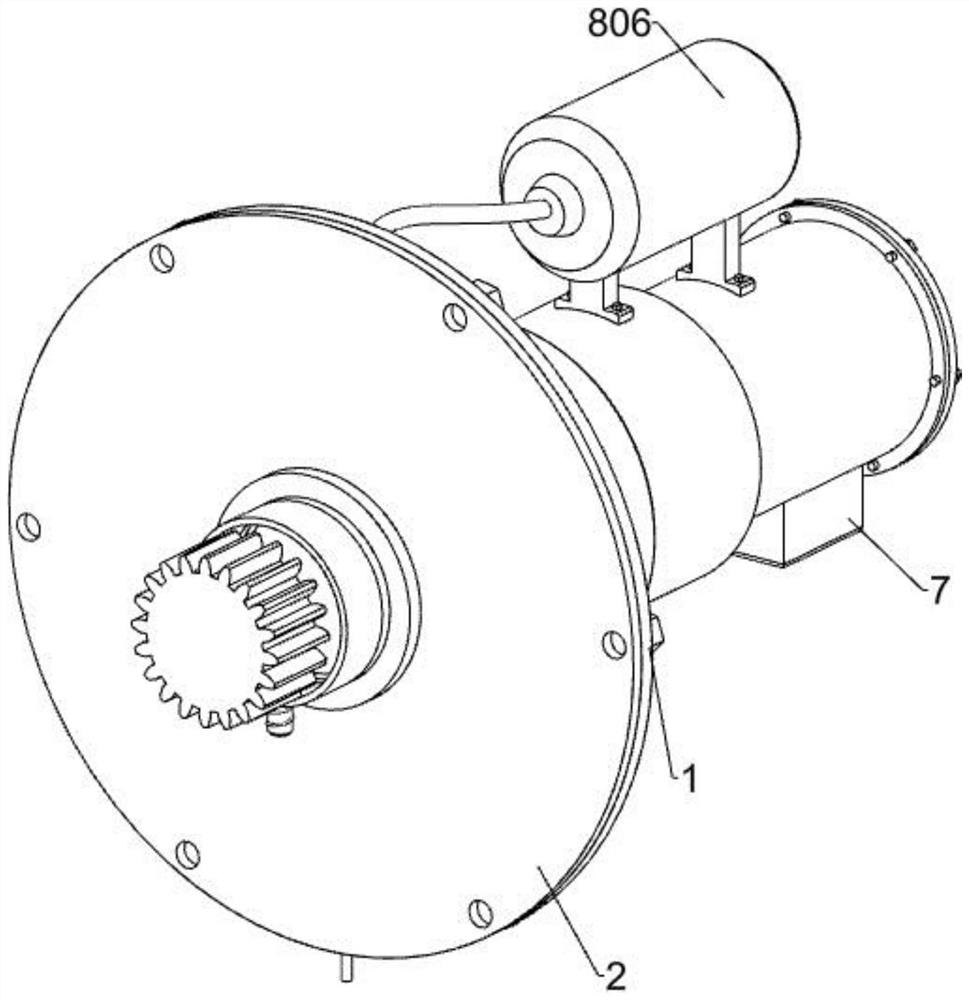
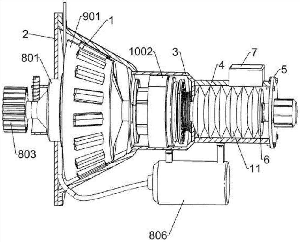
[0034] An anti-fall safety device with automatic grease injection function for elevators, such as Figure 1-Figure 11 As shown, it includes an outer cone 1, a sealing cover 2, a first circular shell 3, a second circular shell 4, a cover plate 5, a copper nut 6, a safety switch 7, an automatic grease injection mechanism, a centrifugal mechanism, and a deceleration adjustment. mechanism, emergency braking mechanism and butterfly spring 11, the front side of the outer cone 1 is fixed with a sealing cover 2, the inner side of the outer cone 1 is installed with a friction belt, and the rear side of the outer cone 1 is connected with a first circle Shape shell 3, the rear side of the first round shell 3 is communicated with a second round shell 4, the rear side of the second round shell 4 is fixed with a cover plate 5, and the copper nut 6 is slidably connected to the second round shell 4 The inner and rear side of the second circular shell 4 is fixed with a safety switch 7 for cutt...
Embodiment 2
[0037] On the basis of Example 1, as figure 2 and image 3 As shown, the automatic grease injection mechanism includes a sealed bearing 801, a rotating shaft 802, a gear 803, a first fixed sleeve 804, a rotational speed sensor 805 and a grease pump 806. The sealed bearing 801 is embedded in the sealing cover 2, and the middle of the sealed bearing 801 is rotatably connected There is a rotating shaft 802, the front end of the rotating shaft 802 is fixed with a gear 803 for engaging with the rack of the lifting frame, the front side of the sealing bearing 801 is fixed with a first fixing sleeve 804, and the upper side of the first fixing sleeve 804 is embedded with A rotation speed sensor 805 for detecting the rotation speed of the rotating shaft 802, a power control switch is installed in the elevator, the rotation speed sensor 805 is electrically connected with the power control switch, and the grease injection pump 806 is fixedly connected to the first circular shell 3 and t...
Embodiment 3
[0048] On the basis of Example 2, as Figure 12-Figure 14 As shown, it also includes an auxiliary deceleration mechanism. The auxiliary deceleration mechanism includes a third fixed sleeve 1201, a second sliding sleeve 1202, a first friction disc 1203, a third spring 1204 and an adjustment component. The third fixed sleeve 1201 is fixed to the first A rear part of the inner side of the circular shell 3, the inner side of the third fixing sleeve 1201 is provided with a spline groove, the inner side of the third fixing sleeve 1201 is splined with a second sliding sleeve 1202, and the front end of the second sliding sleeve 1202 is fixedly connected There is a first friction disc 1203 for friction deceleration, a third spring 1204 is sleeved on the outer side of the third fixing sleeve 1201, and both ends of the third spring 1204 are respectively fixed to the third fixing sleeve 1201 and the first friction disc 1203, The adjusting assembly is fixedly connected to the rear of the i...
PUM
 Abstract
Description
Claims
Application Information
 - R&D
- Intellectual Property
- Life Sciences
- Materials
- Tech Scout
- Unparalleled Data Quality
- Higher Quality Content
- 60% Fewer Hallucinations
Browse by: Latest US Patents, China's latest patents, Technical Efficacy Thesaurus, Application Domain, Technology Topic, Popular Technical Reports.
© 2025 PatSnap. All rights reserved.Legal|Privacy policy|Modern Slavery Act Transparency Statement|Sitemap|About US| Contact US: help@patsnap.com


