Method for operating a brake system of a vehicle, and brake system

a brake system and vehicle technology, applied in the direction of brake systems, vehicle components, braking components, etc., can solve the problems of reduced discharge volume flow, inability to ensure the functioning of the brake system, especially of the abs brake system, and inability to discharge additional brake fluid from the braking device or the braking device, etc., to achieve the effect of reducing the power and reducing the volume flow

Inactive Publication Date: 2015-09-15
ROBERT BOSCH GMBH
View PDF22 Cites 0 Cited by
  • Summary
  • Abstract
  • Description
  • Claims
  • Application Information

AI Technical Summary

Benefits of technology

[0006]One refinement of the present invention provides that the certain operating state is a malfunction of the delivery device and / or the exceeding of a certain fluid level of the intermediate reservoir. In the first case, the discharge volume flow is reduced prophylactically, because it is foreseeable that the delivery device is not able to carry off the brake fluid sufficiently rapidly from the intermediate reservoir or from the braking device into the main brake cylinder. In addition or alternatively, the discharge volume flow may also be reduced upon the exceeding of the certain fluid level. In this way it may be prevented that the intermediate reservoir continues to fill up or fills up too rapidly, and that in this way, at least over a prolonged time span, the complete functioning performance of the brake system is ensured.
[0007]One refinement of the present invention provides that the discharge volume flow, in the case of the malfunction, is selected to be equal to, or less than the maximum delivery volume flow. The maximum delivery volume flow always corresponds to the maximum volume flow at which the brake fluid is able to be returned to the main brake cylinder. In the determination of the maximum delivery volume flow, ideally the malfunction of the delivery device is also taken into account. In this case, the maximum delivery volume flow is determined, for instance, using a model or from measured values. If there is a malfunction, it is meaningful to select the discharge volume flow to be equal, or less than the maximum delivery volume flow, so as to prevent the intermediate reservoir from filling up (too rapidly) and thus impairing the functioning performance of the brake system, at least partially. In this way, under normal conditions, that is, without the presence of the malfunction, the brake system can be used optimally, the delivery device being able to be designed to be smaller than a conventional device, and yet the functioning performance of the brake system is always ensured.
[0013]One refinement of the present invention provides that, for the reduction of the discharge volume flow in a plurality of braking devices, the wheel having the greatest blocking inclination is not taken into account for controlling and / or regulating the brake fluid. Accordingly, in this specific embodiment, a plurality of braking devices is present, each being assigned to one wheel of the vehicle. Normally, at least two of the braking devices are controlled or regulated in common, so that brake fluid is discharged from these simultaneously if only one of the wheels has a certain blocking inclination (“select low” operation). This brings about the greatest driving stability of the vehicle, because the appearance of yaw torques or steering torques is prevented. To be sure, the braking distance of the vehicle also increases, because in the wheel or the wheels, which do not show the highest blocking inclination, only a lower braking force is set, than is possible. However, this “select low” operation also increases the discharge volume flow. In order to decrease this, the “select low” operation is accordingly prevented, and an individual control and / or regulation of each braking device is preferably carried out.

Problems solved by technology

However, this is conditioned upon a comparatively large design of the delivery device.
When it is completely filled up, no additional brake fluid is able to be discharged from the braking device or the braking devices.
Consequently, the functioning of the brake system, particularly of the ABS brake system, cannot be certainly ensured.
In the first case, the discharge volume flow is reduced prophylactically, because it is foreseeable that the delivery device is not able to carry off the brake fluid sufficiently rapidly from the intermediate reservoir or from the braking device into the main brake cylinder.
The malfunction is able to be revealed, for example, by an error in the voltage supply of the delivery device.
However, this “select low” operation also increases the discharge volume flow.

Method used


Image

  • Method for operating a brake system of a vehicle, and brake system
  • Method for operating a brake system of a vehicle, and brake system
  • Method for operating a brake system of a vehicle, and brake system

Examples


Embodiment Construction

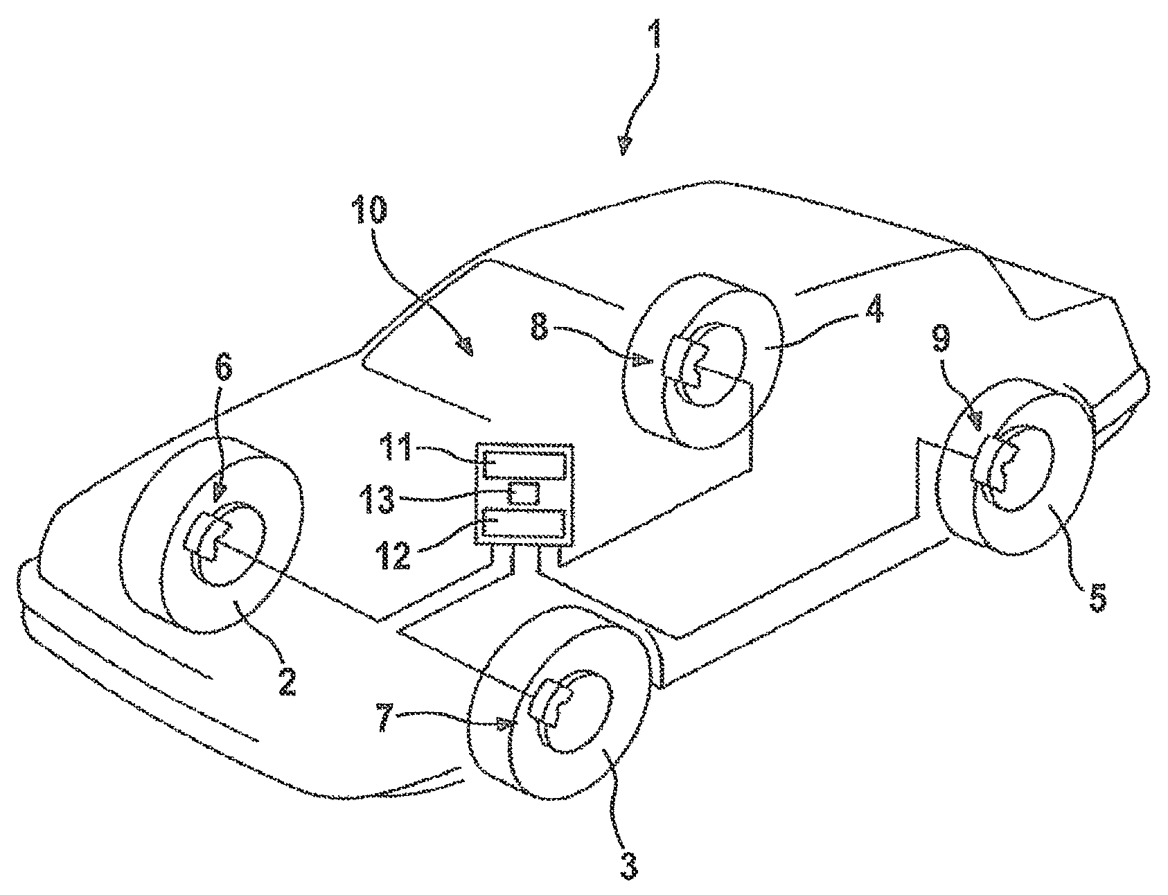
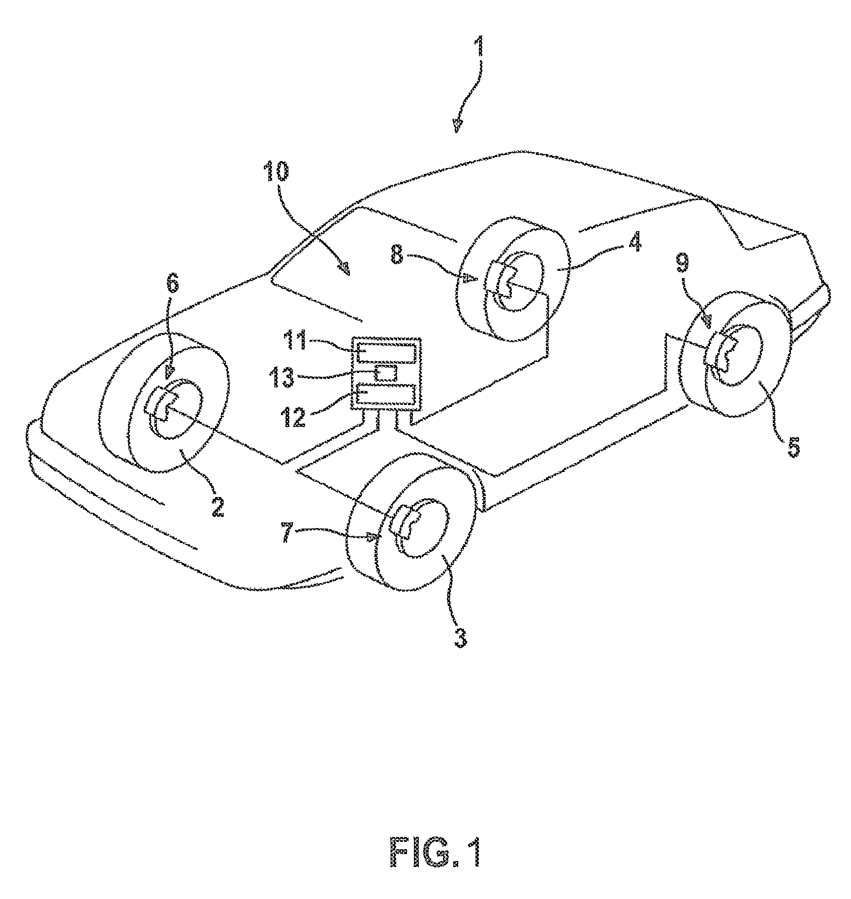
[0018]FIG. 1 shows a vehicle 1 having wheels 2, 3, 4 and 5, to each of which a braking device 6, 7, 8 and 9 has been assigned. Braking devices 6, 7, 8 and 9 are components of a brake system 10 of vehicle 1. Braking devices 6 through 9 are each connected to a main brake cylinder 11, an intermediate reservoir 12, and a delivery device 13.

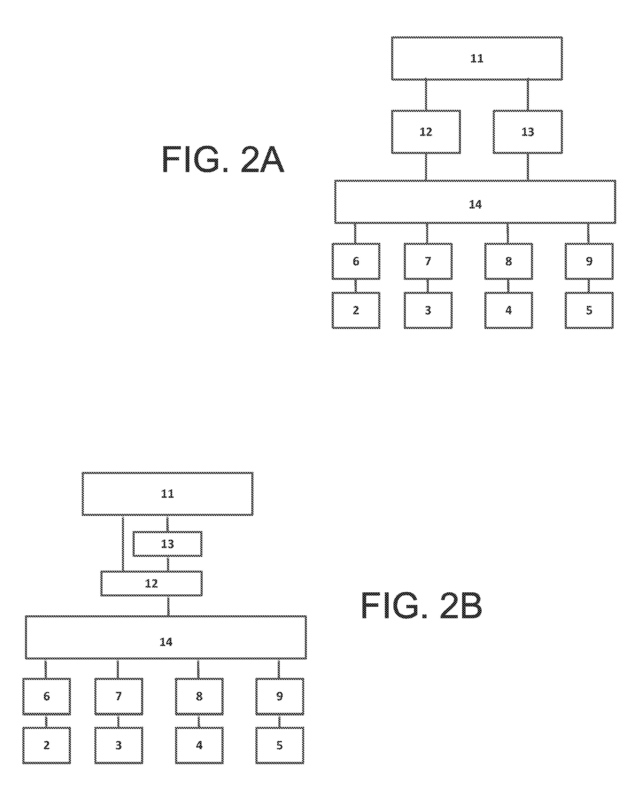
[0019]FIG. 2A and FIG. 2B show alternative embodiments facilitating connections between several components within vehicle 1. Braking devices 6 through 9 are each connected to an intermediate reservoir 12 and a delivery device 13, via a cross-section adjusting member 14. Brake fluid is able to be discharged in a controlled manner from braking devices 6 through 9 via the cross-section adjusting member 14, so as to reduce the braking force exerted on wheels 2 through 5. The brake fluid discharged via cross-section adjusting member 14 in a controlled and / or regulated manner reaches delivery device 13 or intermediate reservoir 12. The volume flow at which ...


PUM


Abstract

A brake system, and a method for operating a brake system of a vehicle. To reduce a braking force, brake fluid is able to be discharged from the braking device via a cross-section adjusting member which connects a delivery device to the braking device, in a controlled and / or regulated manner, into an intermediate reservoir and is delivered to the main brake cylinder using the delivery device. The discharge of the brake fluid from the braking device of the brake system takes place, at least at times, at a discharge volume flow that is greater than the maximum delivery volume flow of the delivery device, and when a certain operating state of the braking system occurs, the discharge volume flow is reduced.

Description

FIELD OF THE INVENTION[0001]The present invention relates to a method for operating a brake system of a vehicle, the brake system having at least one braking device assigned to a wheel of the vehicle, which is provided for applying a braking force to the wheel and to which brake fluid from a main brake cylinder can be supplied, a delivery device connected to the braking device via a cross-section adjusting member and an intermediate reservoir; in order to reduce the braking force, brake fluid being able to be discharged from the braking device via the cross-section adjusting member, in a controlled and / or regulated manner, into the intermediate reservoir and delivered to the main brake cylinder using the delivery device. The present invention further relates to a brake system.BACKGROUND INFORMATION[0002]It is the task of the brake system such as that described above to improve the steering performance and the braking performance, the driving stability and / or the traction of the vehi...

Claims


Application Information

Patent Timeline
Patent Type & Authority Patents(United States)
IPC IPC(8): B60T8/40B60T13/14B60T8/42B60T8/50B60T13/66
CPCB60T13/142B60T8/4275B60T8/4059B60T8/5075B60T13/66
Inventor STREHLE, ALFREDEISELE, ACHIM
Owner ROBERT BOSCH GMBH
Why Eureka
Try Eureka