
Food drying machine facilitating material turning

A technology for drying and turning materials for food is applied in the field of food dryers that are easy to turn materials, which can solve problems such as low efficiency and labor consumption, and achieve the effects of saving raw material resources, turning thoroughly and ensuring quality.

Pending Publication Date: 2022-05-17
安徽沃隆机械设备股份有限公司
View PDF14 Cites 0 Cited by
  • Summary
  • Abstract
  • Description
  • Claims
  • Application Information

AI Technical Summary

Problems solved by technology

[0005] The purpose of the present invention is to solve the problem of labor-intensive and low efficiency in the prior art, and propose a food dryer that is easy to turn over

Method used


Image

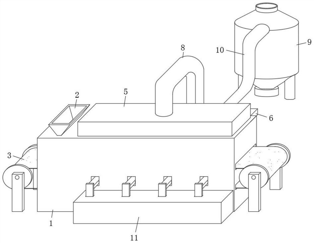
  • Food drying machine facilitating material turning
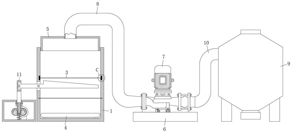
  • Food drying machine facilitating material turning
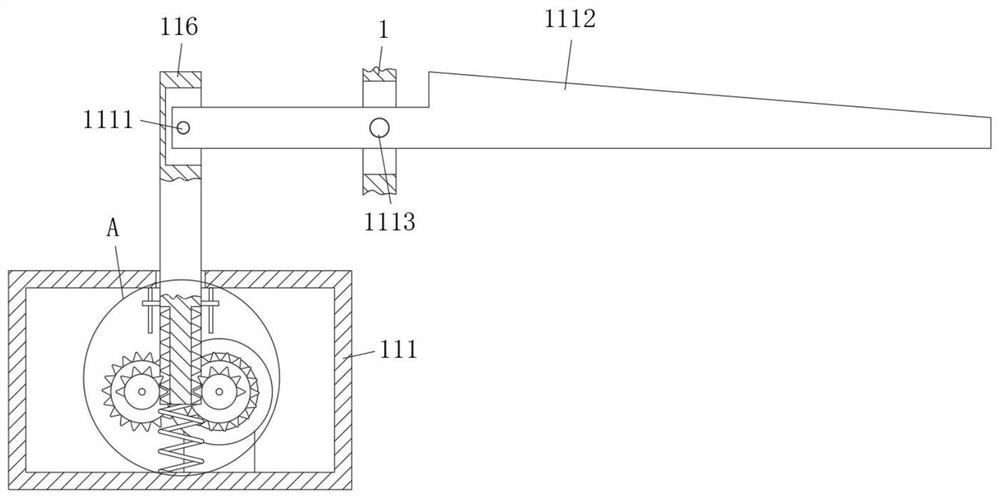
  • Food drying machine facilitating material turning

Examples


Embodiment 1

[0031] refer to figure 1 , 2 And 8, a kind of food drying machine that is convenient for material turning, comprises a drying box 1, a feeding hopper 2 is connected through the top side of the drying box 1, a conveyor belt 3 is installed on the inner side of the drying box 1, and the inside of the drying box 1 The bottom surface is also fixed with an electric heating tube 4, the top surface of the drying box 1 is also connected with a gas collecting dish 5, the rear side of the drying box 1 is also fixed with a mounting seat 6, and the top surface of the mounting seat 6 is fixed with an air pump body 7 by screws. An air extraction pipe 8 is connected between the input end of the air pump body 7 and the top surface of the gas collection dish 5, and a cyclone collector 9 is installed on the rear side of the mounting base 6, and the output end of the air pump body 7 is connected to the input end of the cyclone collector 9. There is an air pipe 10, and a beating mechanism 11 for ...

Embodiment 2

[0034] Such as Figure 1-6As shown, the present embodiment is basically the same as Embodiment 1. Preferably, the beating mechanism 11 includes a drive box 111 installed on the front side of the drying box 1, and the inner walls of both sides of the drive box 111 are rotatably connected with a drive rod 112, and the drive rod 112 There are two and symmetrically distributed on the front and rear sides of the driving box 111, and the two driving rods 112 are rotationally connected by two gear sets with the same specifications. The inner bottom surface of the driving box 111 is also welded with a fixed seat 113. The fixed seat 113 The top surface is fixedly connected with a servo motor 114 by screws, and the output end of the servo motor 114 is fixedly connected with one of the driving rods 112. The outer wall of the driving rod 112 is also fixed with a driving gear 115, and the middle part of the top surface of the driving box 111 is also slidably connected with a driving plate 1...

Embodiment 3

[0037] Such as figure 2 and 7 As shown, this embodiment is basically the same as Embodiment 2. Preferably, the beating plate 1112 includes a horizontal section 1112A and an inclined section 1112B. One side of the drying box 1 is inclined downward toward the side of the mounting seat 6 .

[0038] In this embodiment, the beating plate 1112 is provided with a horizontal section 1112A and an inclined section 1112B, so that the beating plate 1112 can be in close contact with the upper surface of the beveling section 1112B when the beating plate 1112 is beating, thereby increasing the stress area of ​​beating , thus ensuring the quality of material turnover.


PUM


Abstract

The food drying machine comprises a drying box, one side of the top face of the drying box is connected with a feeding hopper in a penetrating mode, a conveying belt is installed on the inner side of the drying box, an electric heating pipe is further fixed to the inner bottom face of the drying box, the top face of the drying box is further connected with a gas collecting vessel in a penetrating mode, and a mounting base is further fixed to the rear side of the drying box; an air pump body is fixed to the top face of the mounting base through screws, an exhaust pipe is connected between the input end of the air pump body and the top face of the air collecting vessel in a penetrating mode, a cyclone collector is further mounted on the rear side of the mounting base, an air conveying pipe is further connected between the output end of the air pump body and the input end of the cyclone collector, and a flapping mechanism used for turning over materials is further mounted on the front side of the drying box. A rectangular groove is further formed in the inner wall of the drying box. The device is reasonable in design and stable in operation, materials are turned over thoroughly during drying, so that the quality of the materials is well guaranteed, hot air is exhausted thoroughly during material drying, and then the material drying efficiency is greatly improved.

Description

technical field [0001] The invention relates to the technical field of food drying equipment, in particular to a food drying machine which is convenient for material turning. Background technique [0002] Food dryers are suitable for industrial and mining enterprises, food processing enterprises, and scientific research units to dry and heat items, so the research on dryers is particularly important. [0003] After searching, the patent with application number 201720293396.2 discloses a material-turning dryer, which includes a body, an inner cavity is provided inside the body, a feeding hopper is arranged on the top of the body, the feeding hopper extends into the inner cavity, and a bottom on one side of the body is set. There is a discharge port, and dryers are installed on both sides of the inner cavity. There are multiple conveyor belts in the inner cavity. There are multiple equidistantly arranged material turning devices above the conveyor belts. The material turning d...

Claims


Application Information

Patent Timeline
Patent Type & Authority Applications(China)
IPC IPC(8): F26B17/04F26B25/02F26B25/04F26B25/00
CPCF26B17/04F26B25/02F26B25/04F26B25/005
Inventor 陈杰来朱志放余龙生王秀娟陈长虹彭钢汪胜明张华葛锋朱军军
Owner 安徽沃隆机械设备股份有限公司
Learn More