Movable hydraulic engineering desilting equipment

A water conservancy engineering, mobile technology, applied in the direction of earth mover/shovel, water/sludge/sewage treatment, mechanically driven excavator/dredger, etc. residual effect

Pending Publication Date: 2022-05-17
江苏省水文水资源勘测局泰州分局
View PDF7 Cites 0 Cited by
  • Summary
  • Abstract
  • Description
  • Claims
  • Application Information

AI Technical Summary

Problems solved by technology

[0003] At this time, it is often necessary to use dredging equipment for water conservancy projects. When the current dredging equipment for water conservancy projects is in use, the position of the dredging head is often fixed. When one area is cleaned, it is often necessary to move to the next area for cleaning. Moreover, there is often a large amount of water remaining in the sludge, which makes it difficult to carry out subsequent collection and processing

Method used


Image

  • Movable hydraulic engineering desilting equipment
  • Movable hydraulic engineering desilting equipment
  • Movable hydraulic engineering desilting equipment

Examples


Embodiment 1

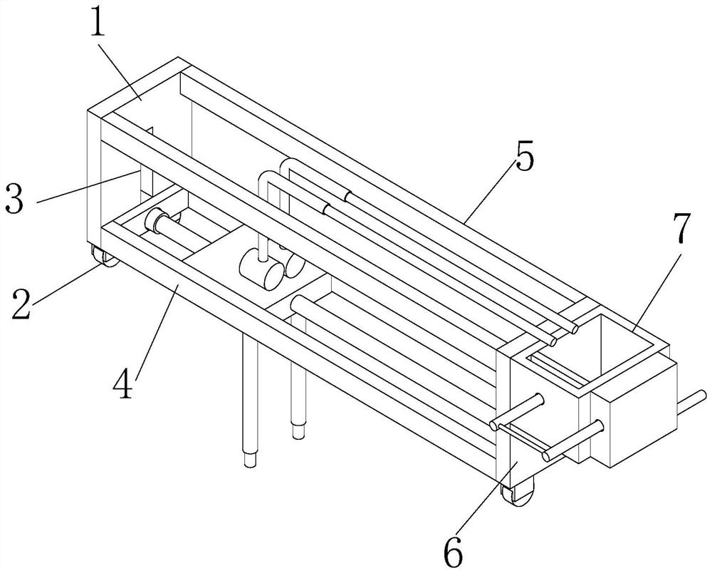
[0030] see figure 1 , the present invention provides a mobile water conservancy dredging equipment through improvement, including a first fixed plate 1, a guide wheel 2, a chute 3, a connecting rod 5, a second fixed plate 6, a lifting and moving mechanism 4 and a collecting squeeze Pressing mechanism 7, the front and rear sides of the bottom of the first fixed plate 1 are oppositely provided with guide wheels 2, the lifting and moving mechanism 4 is embedded and installed on the inside of the first fixed plate 1 and the second fixed plate 6, and the left end of the collection extrusion mechanism 7 is connected to the second fixed plate. The plates 6 are fixedly connected, the right end of the first fixed plate 1 is provided with a chute 3, the first fixed plate 1 is fixedly connected with the left end of the connecting rod 5, and the right end of the connecting rod 5 is fixed with the second fixed plate 6.

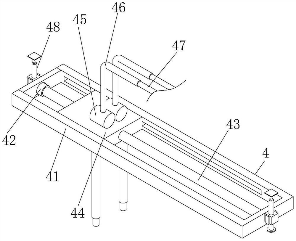
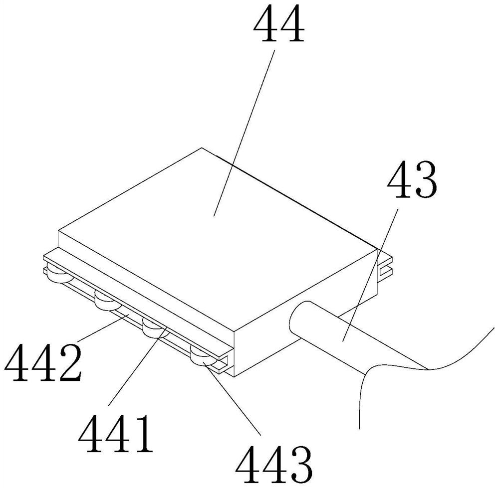
[0031] see figure 2 with image 3 , the present invention provides...

Embodiment 2

[0036] The present invention provides a mobile dredging equipment for water conservancy projects through improvement. The second motor 482, the second screw mandrel 483 and the center line of the moving block 484 are in the same vertical direction, which is beneficial to make the moving block 484 move smoothly. As a function, the moving block 484 is embedded in the inner side of the chute 3, and the moving block 484 is slidably matched with the inner side of the chute 3, which is beneficial to drive the moving frame 41 to move.

[0037] The present invention provides a mobile water conservancy project desilting equipment through improvement, and its working principle is as follows;

[0038] First, before use, place the mobile water conservancy project dredging equipment horizontally so that the guide wheels 2 can support the equipment;

[0039] Second, when in use, by moving the first fixed plate 1 and the second fixed plate 6, the guide wheel 2 is rotated to facilitate the mo...


PUM


Abstract

The invention discloses movable hydraulic engineering desilting equipment which comprises a first fixing plate, a guide wheel, a sliding groove, a connecting rod, a second fixing plate, a lifting moving mechanism and a collecting and extruding mechanism, the lifting moving mechanism is arranged at the upper end of the first fixing plate, a first motor is powered on to work, and a first lead screw is driven to conduct threaded transmission on the inner side of a moving seat; the movable seat is driven to slide on the inner side of the movable frame through the sliding block, so that the movable seat drives the desilting device to move, the desilting position is adjusted, and the advantage that the horizontal desilting position of the desilting device can be rapidly adjusted is achieved; and a telescopic mechanism is arranged at the upper end of the lifting moving mechanism, a second motor is powered on to work, a second lead screw is driven to conduct clockwise thread transmission on the inner side of a moving block, accordingly, the moving block drives a moving frame to move to the lower end, and the advantage that the vertical position of the dredging device can be adjusted is achieved.

Description

technical field [0001] The invention specifically relates to a mobile dredging equipment for water conservancy projects, and relates to related fields of water conservancy projects. Background technique [0002] Water conservancy engineering is a project built to control and allocate natural surface water and groundwater to achieve the purpose of eliminating harm and rejuvenating profits. It is also called water engineering. Water is an indispensable and precious resource for human production and life, but its natural existence The state does not fully meet the needs of human beings. Only by building water conservancy projects can water flow be controlled, floods prevented, and water volume adjusted and distributed to meet the needs of people's life and production for water resources. [0003] At this time, it is often necessary to use dredging equipment for water conservancy projects. When the current dredging equipment for water conservancy projects is in use, the position...

Claims


Application Information

Patent Timeline
Patent Type & Authority Applications(China)
IPC IPC(8): E02F5/28E02F3/88E02F3/90E02F3/92C02F11/121
CPCE02F5/285E02F3/8816E02F3/90E02F3/92C02F11/121
Inventor 吴泽雄张艺铭张彩云王胜艳樊静孟令鹏刘国钧
Owner 江苏省水文水资源勘测局泰州分局
Why Eureka
Try Eureka