A power switch cabinet

A technology for power switches and switch cabinets, applied in the field of power appliances, can solve the problem of inability to switch cabinets

Active Publication Date: 2020-05-26
JIANGXI YAPO ELECTRIC CO LTD
View PDF5 Cites 0 Cited by
  • Summary
  • Abstract
  • Description
  • Claims
  • Application Information

AI Technical Summary

Problems solved by technology

The device cannot level the switchgear on slopes

Method used


Image

  • A power switch cabinet
  • A power switch cabinet
  • A power switch cabinet

Examples


Embodiment Construction

[0028] The following will clearly and completely describe the technical solutions in the embodiments of the present invention with reference to the accompanying drawings in the embodiments of the present invention. Obviously, the described embodiments are only some, not all, embodiments of the present invention. Based on the embodiments of the present invention, all other embodiments obtained by persons of ordinary skill in the art without making creative efforts belong to the protection scope of the present invention.

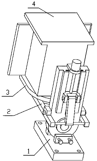
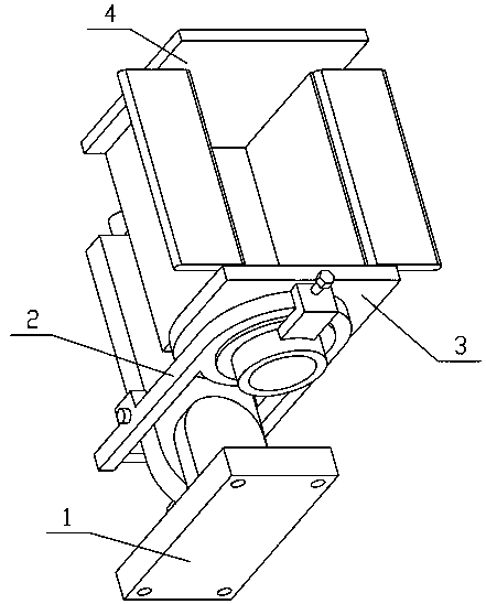
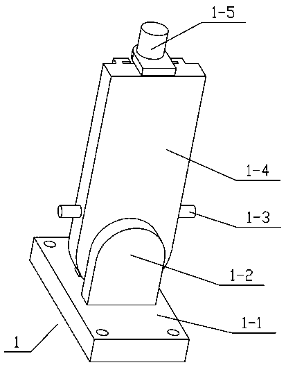
[0029] see Figure 1-8 , the invention provides a technical solution: a power switch cabinet, including a chassis 1, a lifting frame 2, a bottom bracket 3 and a switch cabinet 4, the chassis 1 includes a bottom plate 1-1, a short shaft 1-3, a vertical rotation Plate 1-4, motor 1-5, lead screw 1-6, chute 1-7 and slide block 1-8, the upper end of described base plate 1-1 is provided with described vertical rotating plate 1-4, and described vertical The left and...


PUM


Abstract

The invention discloses a power switch cabinet. The power switch cabinet comprises a bottom frame, a lifting frame, a bottom support and a switch cabinet. The bottom frame comprises a bottom plate, short shafts, a vertical rotation plate, a motor, a screw, a chute and a sliding block. The upper end of the bottom plate is provided with the vertical rotation plate, left and right ends of the lower end of the vertical rotation plate are respectively fixedly connected with the short shafts, the upper end of the vertical rotation plate is fixedly connected with the motor, an output shaft at the lower end of the motor is fixedly connected with the screw, the rear side of the vertical rotation plate is provided with the chute, the sliding block is slidingly connected on the chute, and the screw is matched with the sliding block through screw threads.

Description

technical field [0001] The invention relates to an electric appliance, in particular to an electric switch cabinet. Background technique [0002] A current electric switch cabinet includes a cabinet body and a plurality of installation boxes installed in the cabinet body for installing switching components, and rollers are installed at the front end of each of the lower end faces and upper end faces of each of the installation boxes, Slide blocks are installed on the rear end of the lower end surface and the upper end surface of each of the installation boxes, and the bottom wall and top wall of the cabinet body are provided with front and rear sliding grooves that cooperate with the sliding blocks and rollers and extend forward and backward. The front end parts of the body bottom wall and the top wall are provided with left and right sliding grooves extending left and right, the front and rear sliding grooves communicate with the left and right sliding grooves, and the fron...

Claims


Application Information

Patent Timeline
Patent Type & Authority Patents(China)
IPC IPC(8): H02B1/30H02B1/20H02B1/28H02K7/06
CPCH02B1/20H02B1/28H02B1/30H02K7/06
Inventor 杨和茂刘正勇龚建国周学军王和平文方杨俊卿刘国荣余定飞甘义邓阳
Owner JIANGXI YAPO ELECTRIC CO LTD
Why Eureka
Try Eureka