Capacitance isolation type miniature solid state relay
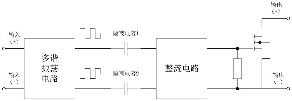
A solid-state relay and capacitive isolation technology, applied in electronic switches, electrical components, pulse technology, etc., can solve the problems of large size, difficulty in integration and miniaturization design, and achieve the effect of simplifying the circuit, improving driving efficiency, and increasing the range
- Summary
- Abstract
- Description
- Claims
- Application Information
AI Technical Summary
Problems solved by technology
Method used
Image
Examples
Embodiment 1
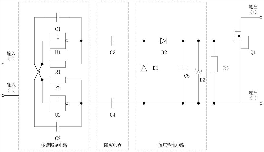
[0021] see figure 2 , a capacitively isolated miniature solid state relay, is composed of a multivibrator circuit, an isolation capacitor, a rectifier circuit and an output FET circuit. The multivibrator circuit is composed of NOT gates U1~U2, resistors R1~R2, and capacitors C1~C2. The isolation capacitor is composed of capacitors C3-C4. The rectification circuit is a voltage doubler rectification circuit, which is composed of diodes D1-D2, capacitor C5 and voltage-stabilizing diode D3. The output field effect tube circuit is composed of resistor R3 and field effect tube Q1.
[0022] The positive and negative terminals of the power supply of the NOT gates U1 and U2 are respectively the positive and negative terminals of the solid state relay. The input terminal and output terminal of the NOT gate U1 are respectively connected to both ends of the resistor R1, the output terminal of the NOT gate U1 is connected to one terminal of the capacitor C1, and the other terminal of t...
Embodiment 2
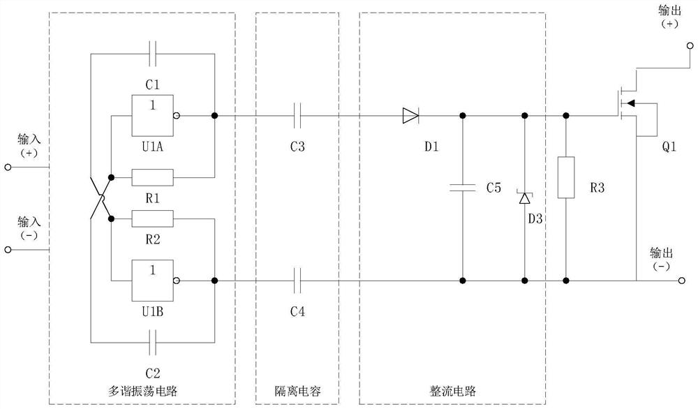
[0027] see image 3 , a capacitively isolated miniature solid state relay, is composed of a multivibrator circuit, an isolation capacitor, a rectifier circuit and an output FET circuit. The multivibrator circuit is composed of NOT gates U1~U2, resistors R1~R2, and capacitors C1~C2. The isolation capacitor is composed of capacitors C3-C4. The rectification circuit is a half-wave rectification circuit, which is composed of diode D4, capacitor C6 and Zener diode D5. The output field effect tube circuit is composed of resistor R3 and field effect tube Q1.
[0028] The positive and negative terminals of the power supply of the NOT gates U1 and U2 are respectively the positive and negative terminals of the solid state relay. The input terminal and output terminal of the NOT gate U1 are respectively connected to both ends of the resistor R1, the output terminal of the NOT gate U1 is connected to one terminal of the capacitor C1, and the other terminal of the capacitor C1 is connec...
Embodiment 3
[0033] see Figure 4 , a capacitively isolated miniature solid state relay, is composed of a multivibrator circuit, an isolation capacitor, a rectifier circuit and an output FET circuit. The multivibrator circuit is composed of Schmitt trigger NOT gates U1A-U1B, resistor R1, and capacitor C1. The isolation capacitor is composed of capacitors C3-C4. The rectification circuit is a voltage doubler rectification circuit, which is composed of diodes D1-D2, capacitor C5 and voltage-stabilizing diode D3. The output field effect tube circuit is composed of resistor R3 and field effect tube Q1.
[0034]The positive and negative terminals of the power supply of the Schmitt trigger NOT gate U1A and the Schmitt trigger NOT gate U1B are respectively the positive and negative input terminals of the solid state relay. The input terminal of the Schmitt trigger NOT gate U1A is connected to the capacitor C1 and one end of the resistor R1; the other end of the capacitor C1 is grounded; the ot...
PUM
 Abstract
Description
Claims
Application Information
 - R&D Engineer
- R&D Manager
- IP Professional
- Industry Leading Data Capabilities
- Powerful AI technology
- Patent DNA Extraction
Browse by: Latest US Patents, China's latest patents, Technical Efficacy Thesaurus, Application Domain, Technology Topic, Popular Technical Reports.
© 2024 PatSnap. All rights reserved.Legal|Privacy policy|Modern Slavery Act Transparency Statement|Sitemap|About US| Contact US: help@patsnap.com


