
Dust removal equipment with dust suppression structure

A technology of dust removal equipment and dust remover, which is applied in the field of dust removal, can solve problems such as not taking into account, not setting up protective structures, flying dust, etc., and achieve the effect of improving wear resistance

Pending Publication Date: 2022-05-13
JIANGSU GUIMING MACHINERY
View PDF4 Cites 0 Cited by
  • Summary
  • Abstract
  • Description
  • Claims
  • Application Information

AI Technical Summary

Problems solved by technology

The high-efficiency, energy-saving and environment-friendly dust removal equipment can separately filter the large particles and small particles in the exhaust gas passing into the main body of the dust removal device by setting the first filter screen and the second filter screen inside the main body of the dust removal device, and set an activated carbon filter box , can filter the relatively fine particles and odors in the exhaust gas, and achieve the purpose of high-efficiency, energy-saving, environmental protection and dust removal. However, the dust removal equipment in the above-mentioned open documents mainly considers the adsorption and filtration of fine particles and odors in the flue gas, and does not take into account the existing Some dust removal equipment does not have a protective structure when cleaning, and it is very easy for the dust to move upward and be discharged from the exhaust pipe;
[0006] 3. The patent document CN210674532U discloses a kind of indoor dust removal equipment for green buildings, which relates to the technical field of dust removal equipment. In order to solve the problem that the internal components of dust removal used in the existing indoor dust removal equipment for green buildings are all filter plates, the penetration of such dust Permeability has certain limitations. The traditional filter plate needs to be taken out and replaced, which is not easy to operate.
The utility model is equipped with a cleaning brush plate with a cleaning brush on the filter screen inside the dust removal equipment body, and the cleaning brush plate is rotatably connected with the connecting shaft on the filter screen, and is driven to rotate by the driving gear on the drive motor, and However, the dust removal equipment in the above-mentioned public documents mainly considers how to clean the filter screen, and does not take into account that most of the existing dust removal equipment discharges the dust directly on the ground after dedusting, and it is extremely difficult during the discharge process. Prone to flying dust

Method used


Image

  • Dust removal equipment with dust suppression structure
  • Dust removal equipment with dust suppression structure
  • Dust removal equipment with dust suppression structure

Examples


Embodiment Construction

[0039] The following will clearly and completely describe the technical solutions in the embodiments of the present invention with reference to the accompanying drawings in the embodiments of the present invention. Obviously, the described embodiments are only some, not all, embodiments of the present invention. Based on the embodiments of the present invention, all other embodiments obtained by persons of ordinary skill in the art without making creative efforts belong to the protection scope of the present invention.

[0040] In the description of the present invention, it should be noted that the terms "upper", "lower", "inner", "outer", "front end", "rear end", "both ends", "one end", "another end" The orientation or positional relationship indicated by etc. is based on the orientation or positional relationship shown in the drawings, and is only for the convenience of describing the present invention and simplifying the description, rather than indicating or implying that ...


PUM


Abstract

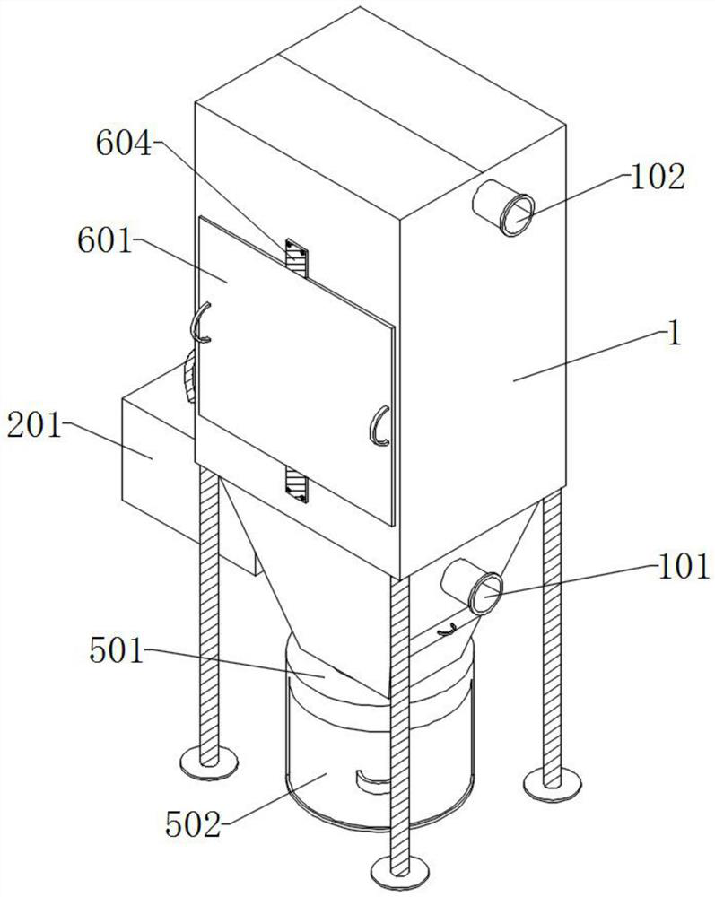
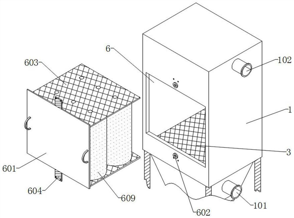
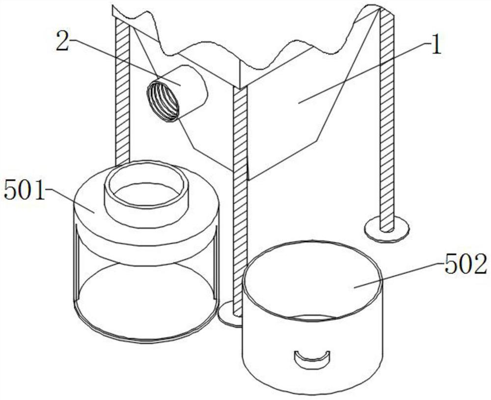
The dust removal equipment with the dust suppression structure comprises a dust removal machine body and a first connecting pipe, the first connecting pipe is installed on the outer wall of one side of the dust removal machine body, and a storage box is installed at one end of the first connecting pipe; a partition plate is installed on the bottom wall of the storage box, a water inlet pipe and a water pump are installed on the top of the storage box, a storage box is installed on the bottom wall of the storage box and located on one side of the partition plate, a servo motor is installed on the bottom wall of the storage box, and a stirring rod is installed at the output end of the servo motor. A sliding groove is formed in the top of the storage box in a penetrating mode, a liquid conveying steel pipe is installed at the output end of the water pump, and a nozzle is installed at one end of the liquid conveying steel pipe. By arranging the first connecting pipe, the storage box, the water pump and the nozzle, a biological nano-membrane is sprayed into the dust remover main body through the nozzle in use, so that the biological nano-membrane can collide with entering dust, and the purpose of dust suppression is achieved.

Description

technical field [0001] The invention relates to the technical field of dust removal, in particular to a dust removal device with a dust suppression structure. Background technique [0002] Dust removal equipment refers to equipment that separates dust from the flue gas, but the existing dust removal equipment mainly draws the flue gas into the interior of the dust removal equipment through the dust inlet pipe, and then absorbs and filters the dust in the flue gas layer by layer. After the impurities are adsorbed, the clean flue gas is discharged through the exhaust pipe. However, the existing dust removal equipment still has major defects during use. Therefore, a dust removal equipment with a dust suppression structure is urgently needed. [0003] The defective that existing dedusting equipment exists is: [0004] 1. Patent document CN214287342U discloses a gas dedusting device, including a base, the top surface of the base is provided with a box for dust removal, and the b...

Claims


Application Information

Patent Timeline
IPC IPC(8): B03C3/017B01D50/60
CPCB03C3/017
Inventor 张宏林
Owner JIANGSU GUIMING MACHINERY
Learn More