


Quick Research
Generate reliable direction feasibility study reports for your R&D in just a few steps.

Technical Q&A
Discover and master advanced knowledge NOW. Basics, ideas, possibilities, all at once.

Find Solutions
As an expert in R&D theories, this can generate solutions to your technical problems instantly.

Evaluate Feasibility
Analyze your overall solution with one click, know your potential R&D risks in advance.

Monitor Landscape
Get weekly tech updates, stay abreast of the latest tech innovations and key insights.
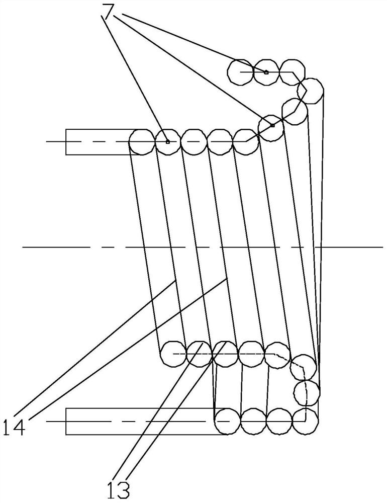
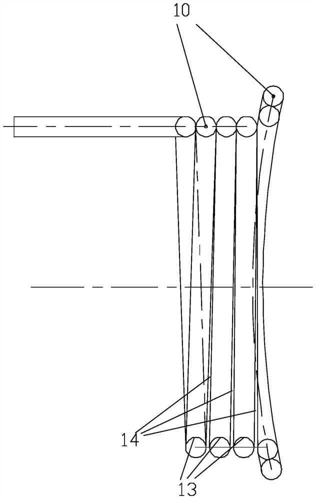
Combined burner cooling cover device
A burner cover and cooling cover technology, which is applied in the field of coal gasification, can solve the problems of unimproved working environment of the surrounding furnace water wall, bad working environment of the burner cover, difficult maintenance, etc., so as to avoid flame drift, reduce economic losses, The effect of reducing the maintenance period
- Summary
- Abstract
- Description
- Claims
- Application Information
AI Technical Summary
Problems solved by technology
Method used
Image


Examples
Embodiment Construction
[0032] Below, specific embodiments of the present invention will be described in detail in conjunction with the accompanying drawings, but they are not intended to limit the present invention. In order to enable those skilled in the art to better understand the technical solutions of the present disclosure, the present disclosure will be described in detail below in conjunction with the accompanying drawings and specific embodiments. Embodiments of the present disclosure will be described in further detail below in conjunction with the accompanying drawings and specific embodiments, but are not intended to limit the present disclosure.
[0033] All terms (including technical terms or scientific terms) used in the present disclosure have the same meaning as understood by one of ordinary skill in the art to which the present disclosure belongs, unless otherwise specifically defined. It should also be understood that terms defined in, for example, general-purpose dictionaries sho...
PUM
 Abstract
Description
Claims
Application Information
 - R&D Engineer
- R&D Manager
- IP Professional
- Industry Leading Data Capabilities
- Powerful AI technology
- Patent DNA Extraction
Browse by: Latest US Patents, China's latest patents, Technical Efficacy Thesaurus, Application Domain, Technology Topic, Popular Technical Reports.
© 2024 PatSnap. All rights reserved.Legal|Privacy policy|Modern Slavery Act Transparency Statement|Sitemap|About US| Contact US: help@patsnap.com