
Intelligent fire-fighting linkage system of photovoltaic booster station and matched energy storage power station

A technology of fire protection system and energy storage power station, which is applied in the direction of electric transmission signal system, substation/power distribution device shell, electrical components, etc., which can solve the problems of low fire extinguishing efficiency, inability to monitor fire alarm status in real time or in a timely manner, and increase safety hazards, etc. , to achieve the effects of saving construction and land costs, reducing the impact of fire expansion, and reducing operation and maintenance costs

Pending Publication Date: 2022-05-10
JIANGXI THERMAL POWER CONSTR CORP
View PDF8 Cites 1 Cited by
  • Summary
  • Abstract
  • Description
  • Claims
  • Application Information

AI Technical Summary

Problems solved by technology

[0005] 1. The fire monitoring and alarm system in the container is independent and scattered. There is no unified control and management of the fire protection system of the photovoltaic booster station and the energy storage power station. ;
[0006] 2. The fire extinguishing system of the battery container is to extinguish the fire for the entire container space, but not for the fire point, resulting in waste of reagents, low fire extinguishing efficiency, and certain impact on the normal battery pack;
[0007] Clean gas fire extinguishing agents such as heptafluoropropane or perfluorohexanone have a good effect on extinguishing open flames, but they cannot cool down the battery for a long time, and the method of spraying gas fire extinguishing agents still has the risk of re-ignition

Method used


Image

  • Intelligent fire-fighting linkage system of photovoltaic booster station and matched energy storage power station

Examples


Embodiment Construction

[0032] The following will clearly and completely describe the technical solutions in the embodiments of the present invention with reference to the drawings in the embodiments of the present invention.

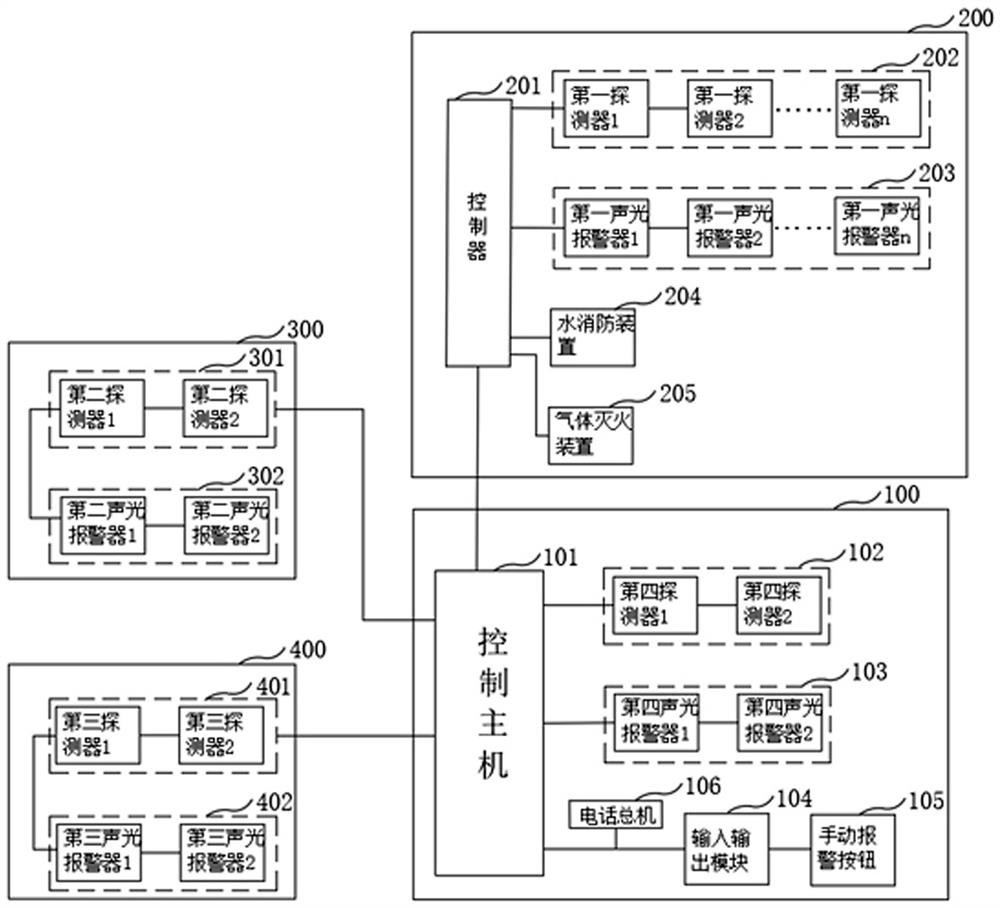
[0033] like figure 1 As shown, this embodiment provides a smart fire protection linkage system of a photovoltaic booster station and a supporting energy storage power station, including a main firefighting system 100 of a photovoltaic booster station, a sub-firefighting system 200 of an energy storage battery container, and a firefighting system 300 of a PCS booster box and the four parts of EMS centralized control box fire protection system 400, install a photovoltaic booster station main fire protection system control host 101 in the main control room of the photovoltaic booster station, and connect the photovoltaic booster station main fire protection system 100 with the battery container in the energy storage station, The PCS step-up integrated box, EMS centralized control...


PUM


Abstract

The invention discloses an intelligent fire-fighting linkage system of a photovoltaic booster station and a matched energy storage power station. The intelligent fire-fighting linkage system comprises an energy storage battery container fire-fighting sub-system, wherein the energy storage battery container fire-fighting sub-system comprises a controller, and a first audible and visual alarm, a first detector, a water fire-fighting device and a gas fire-extinguishing device which are connected with the controller; the PCS booster box fire extinguishing system comprises a plurality of second detectors and a second audible and visual alarm; the EMS centralized control box fire extinguishing system comprises a plurality of third detectors and a third audible and visual alarm; the photovoltaic booster station main fire extinguishing system comprises a control host, a plurality of fourth detectors, a fourth audible and visual alarm and a manual alarm button. The control host is connected with the detectors, the audible and visual alarm, the manual alarm button and the controller. Linkage design is carried out on the main fire extinguishing system of the photovoltaic booster station, the battery container, the PCS booster integrated box, the EMS centralized control box and other sub fire extinguishing systems, alarm signals are received / monitored in a unified mode, and output management is controlled in a unified mode.

Description

technical field [0001] The invention relates to the technical field of fire treatment, in particular to a smart fire-fighting linkage system of a photovoltaic booster station and a supporting energy storage power station. Background technique [0002] The existing design schemes for the fire protection system of energy storage power stations on the new energy side are often more focused on the fire safety inside the energy storage lithium battery container, without comprehensive consideration and realization of the fire linkage and unified control of the "new energy + energy storage" power station. Photovoltaic booster stations mainly include booster main transformers, station transformers, SVG equipment, secondary equipment prefabricated cabins, electrical buildings (electrical equipment such as switch cabinets), comprehensive operation and maintenance buildings, etc.; energy storage power stations mainly include battery containers, PCS Pressure box, EMS centralized control...

Claims


Application Information

Patent Timeline
Patent Type & Authority Applications(China)
IPC IPC(8): A62C3/16A62C31/00A62C31/28A62C37/00G08B7/06H02B1/28H02J13/00
CPCA62C3/16A62C37/00A62C31/005A62C31/28H02B1/28H02J13/00002G08B7/06A62C99/0072A62C99/0018
Inventor 王雅丽熊建英谢光辉周灿煌罗俊达
Owner JIANGXI THERMAL POWER CONSTR CORP
Learn More