Neurosurgery ventricular drainage tube clamping device

A technique for ventricular drainage and neurosurgery, which is applied to catheters, suction devices, and drug devices to achieve the effects of simple and fast operation, firm fixation, and strong practicability.

Active Publication Date: 2022-05-10
HENAN PROVINCE HOSPITAL OF TCM THE SECOND AFFILIATED HOSPITAL OF HENAN UNIV OF TCM
View PDF7 Cites 0 Cited by
  • Summary
  • Abstract
  • Description
  • Claims
  • Application Information

AI Technical Summary

Problems solved by technology

[0010] In view of the above situation, in order to overcome the defects of the prior art, the present invention provides a neurosurgery ventricle drainage tube clamping device, which effectively solves the problems existing when using adhesive tape and gauze to fix the drainage tube

Method used


Image

  • Neurosurgery ventricular drainage tube clamping device
  • Neurosurgery ventricular drainage tube clamping device
  • Neurosurgery ventricular drainage tube clamping device

Examples


Embodiment 1

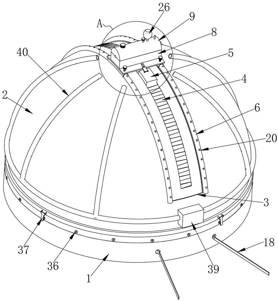
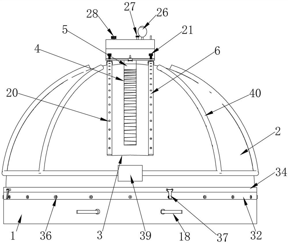
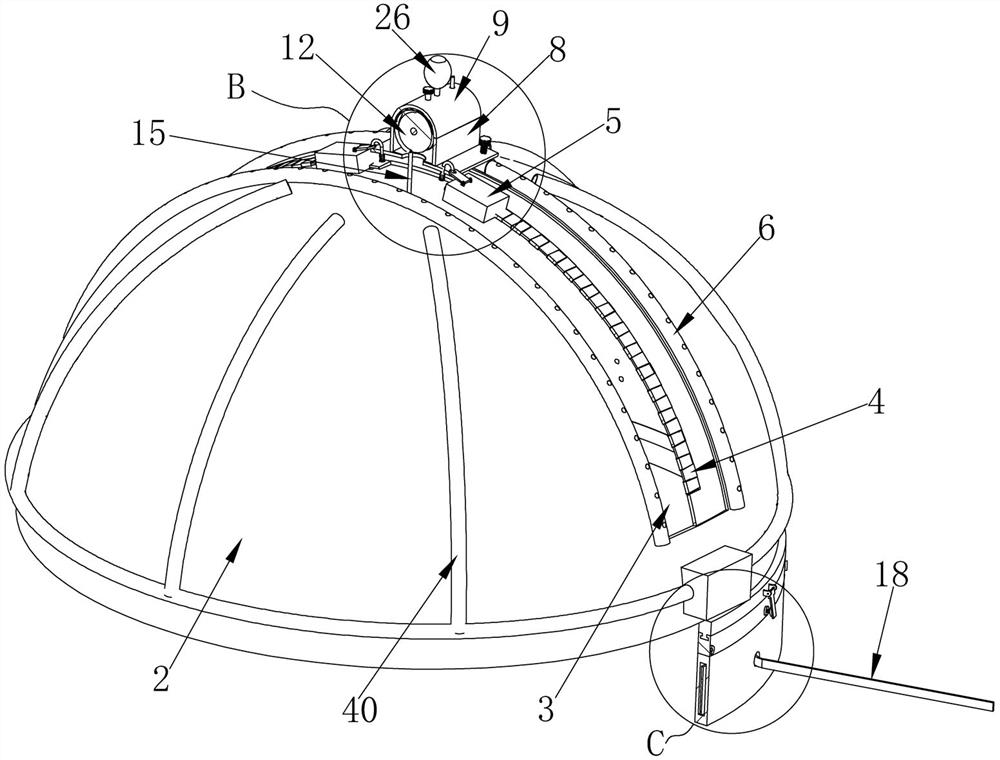
[0039]Embodiment 1. The present invention is a neurosurgery ventricular drainage tube clamping device, which includes a ring-shaped elastic band 1. The material of the elastic band 1 is cloth, which is elastic and can be expanded when pulled hard. The top of the elastic band 1 is the same as The shaft is rotatably connected with a covering cap 2 that is bowl-shaped and has a hollow bottom opening inside. The covering cap 2 can rotate on the top of the elastic band 1. The material of the covering cap 2 is non-woven fabric or other compliant breathable cloth material , the covering cap 2 can be worn on the patient's head through the elastic band 1, after wearing the covering cap 2, the elastic band 1 is tightly wrapped around the head, the inner side of the covering cap 2 is close to the patient's scalp, and the covering cap 2 A liquid-absorbing cloth can be pasted on the inner side, which can absorb the liquid overflowing from the drainage site. The pasted liquid-absorbing cloth...

Embodiment 2

[0040] Embodiment two, on the basis of embodiment one, the inside of described elastic band 1 is equipped with elastic rubber band 17, and elastic rubber band 17 provides elastic force for elastic band 1, and the inside of described elastic band 1 is worn with elastic rope 18, and described elastic cord The two ends of 18 run through the front side of the elastic band 1 respectively, and when the covering cap 2 is worn on the head, it can be firmly fixed by tightening the elastic cord 18 .

Embodiment 3

[0041] Embodiment 3, on the basis of Embodiment 1, the left and right ends of the bottom of the clamping slide 7 are respectively fixed with arc-shaped slide plates 19 that slide and fit with the two circular slide rails 6, and the arc-shaped slide plates 19 Sliding on the circular slide rail 6, thereby driving the clamping slide 7 to slide, the outer surfaces of the two circular slide rails 6 are respectively provided with a plurality of positioning holes 20, and the tops of the clamping slide 7 are respectively There are threaded holes running through the two arc-shaped slide plates 19, and the two threaded holes are respectively threaded with positioning bolts 21. After the position of the clamping slide 7 is determined, the positioning bolts 21 can be screwed into the corresponding positioning holes 20 The interior is positioned, and now the clamping slide 7 will not be able to move.


PUM


Abstract

The invention provides a ventricular drainage tube clamping device for the neurosurgery department. The ventricular drainage tube clamping device solves the problems existing when a drainage tube is fixed through adhesive tape and gauze. Comprising an elastic band, the top of the elastic band is connected with a covering cap, an operation groove penetrates through the covering cap, a zipper is connected into the operation groove, two circular sliding rails are fixedly installed on the outer surface of the covering cap, a clamping sliding seat is slidably installed on the two circular sliding rails, a winding box is installed on the top of the clamping sliding seat, and a winding cover is hinged to the top of the winding box; semicircular grooves are formed in the left side face and the right side face of the winding box and the left side face and the right side face of the winding cover, winding rollers are coaxially installed in the two semicircular grooves, winding spiral grooves are formed in the winding rollers, drainage pipes are wound in the winding spiral grooves, and an air bag is fixedly installed on the inner side face of the winding cover. The drainage tube can be embedded in the winding spiral groove in the winding roller, the winding roller is fixed, when the drainage tube is pulled, the winding roller cannot rotate, the drainage tube cannot slide in the winding spiral groove, and soft fixing of the drainage tube is achieved.

Description

technical field [0001] The invention relates to the technical field of medical instruments, in particular to a neurosurgery ventricle drainage tube clamping device. Background technique [0002] When the intracranial volume increases due to a variety of pathogenic factors, and the cerebrospinal fluid pressure measured by lumbar puncture in the lateral position exceeds 1.92kpa, it means increased intracranial pressure. If headache, vomiting, visual impairment, papilledema, etc. When clinically manifested, it is called the syndrome of increased intracranial pressure. According to the principle of Monroe-kellie, in addition to the blood vessels communicating with the extracranial, the cranial cavity, including the connected spinal cavity, can basically be regarded as a non-expandable container. is constant. [0003] There are three kinds of contents in the cranium, namely, brain tissue, blood and cerebrospinal fluid. Although their volumes cannot be compressed, they can compen...

Claims


Application Information

Patent Timeline
Patent Type & Authority Applications(China)
IPC IPC(8): A61M25/02A61M1/00
CPCA61M25/02A61M2025/0206A61M2025/0213A61M2025/0246A61M2025/0253A61M2025/028A61M2210/0687A61M2210/005
Inventor 刘彪郑慧军曹勇谢磊杜康
Owner HENAN PROVINCE HOSPITAL OF TCM THE SECOND AFFILIATED HOSPITAL OF HENAN UNIV OF TCM
Why Eureka
Try Eureka