Eureka AIR delivers breakthrough ideas for toughest innovation challenges, trusted by R&D personnel around the world.

Switching device and feedback resistance circuit

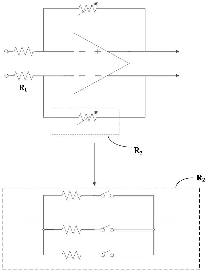
A switching device and circuit technology, which can be used in electronic switches, parts of amplifying devices, electrical components, etc., and can solve problems such as low bandwidth of PGA

Active Publication Date: 2022-05-06
广州瀚辰信息科技有限公司
View PDF10 Cites 0 Cited by
  • Summary
  • Abstract
  • Description
  • Claims
  • Application Information

AI Technical Summary

Problems solved by technology

[0003] The inventor found that the existing PGA has the problem of low bandwidth

Method used


Image

  • Switching device and feedback resistance circuit
  • Switching device and feedback resistance circuit
  • Switching device and feedback resistance circuit

Examples


Embodiment Construction

[0042] In order to facilitate the understanding of the present application, the present application will be described more fully below with reference to the relevant drawings. Embodiments of the application are given in the drawings. However, the present application can be embodied in many different forms and is not limited to the embodiments described herein. On the contrary, the purpose of providing these embodiments is to make the disclosure of this application more thorough and comprehensive.

[0043]Unless otherwise defined, all technical and scientific terms used herein have the same meaning as commonly understood by one of ordinary skill in the technical field to which this application belongs. The terms used herein in the specification of the application are only for the purpose of describing specific embodiments, and are not intended to limit the application.

[0044] It can be understood that the terms "first", "second" and the like used in this application may be ...


PUM


Abstract

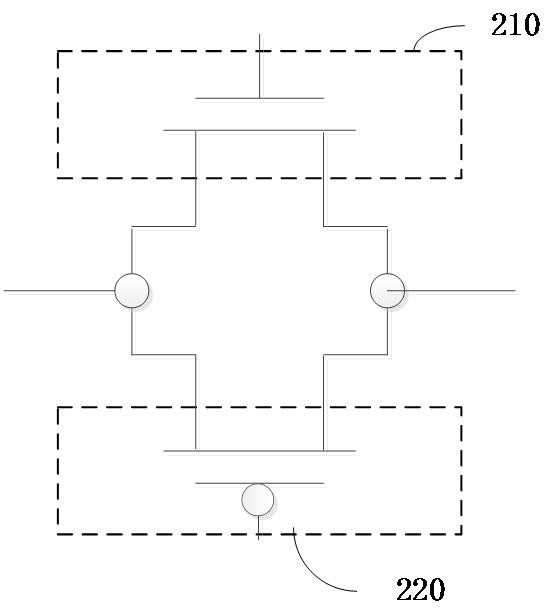
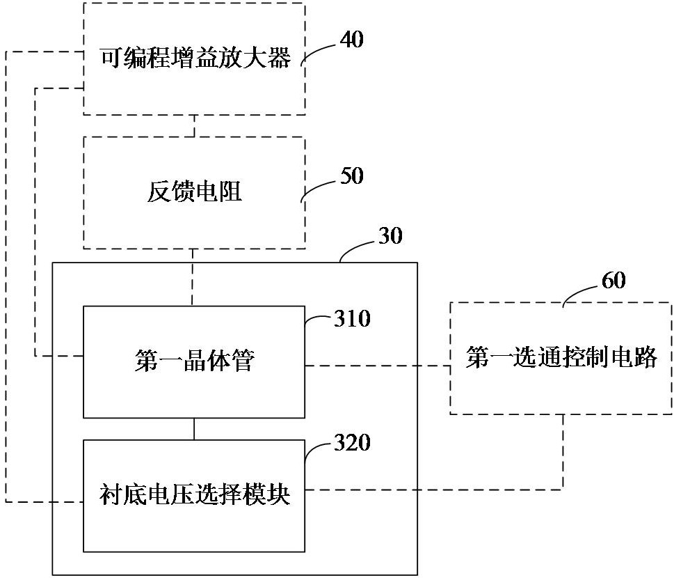
The invention relates to a switching device and a feedback resistance circuit. The device is characterized in that a first transmission end of a first transistor is used for connecting an input end of an operational amplifier; the second transmission end of the first transistor is connected with the output end of the operational amplifier through a feedback resistor; the control end of the first transistor is used for being connected with a first gate control circuit, responding to a first gate control signal output by the first gate control circuit and entering a gate state or a turn-off state; the output end of the substrate voltage selection module is connected with the third transmission end of the first transistor, one input end of the substrate voltage selection module is used for being connected with the input end of the operational amplifier, and the control end of the substrate voltage selection module is used for being connected with the first gating control circuit; and the substrate voltage selection module is used for transmitting the input voltage of the operational amplifier to the substrate of the first transistor under the condition that the first transistor is in the gating state. By adopting the device, the bandwidth of the programmable gain amplifier can be improved.

Description

technical field [0001] The invention relates to the technical field of receiver signal processing, in particular to a switch device and a feedback resistance circuit. Background technique [0002] In the receiver system, the signal received by the receiver varies greatly. In order to demodulate the received signals with different strengths, the system uses AGC (Automatic Gain Control, automatic gain control circuit) to control the PGA (Programmable Gain Amplifier, programmable gain amplifier) ) to keep the output signal at a certain level, and the gain adjustment step generally needs to achieve decibel (dB) linearity. PGA generally uses programmable resistors to adjust the gain. By changing the feedback resistor, the ratio between the feedback resistor and the input resistor can be changed, so as to realize the change of the circuit gain. In the mainstream CMOS process, MOS transistors are generally used as switches to adjust the resistance value, or the MOS switches are se...

Claims


Application Information

Patent Timeline
Patent Type & Authority Applications(China)
IPC IPC(8): H03K17/687H03F1/48H03F1/56H03F3/195H03F3/213
CPCH03K17/687H03F1/486H03F1/56H03F3/195H03F3/213H03F2200/36
Inventor 王祥炜李金明刘渭陈红林
Owner 广州瀚辰信息科技有限公司
Why Eureka
Eureka Blog
Learn More