
Multifunctional metal material detection device

A technology of metal materials and detection devices, applied in the direction of measuring devices, mechanical measuring devices, analyzing materials, etc., can solve the problem of simultaneous detection of the weight and hardness of metal materials, etc.

Inactive Publication Date: 2022-05-06
苏州捭源金属材料科技有限公司
View PDF0 Cites 1 Cited by
  • Summary
  • Abstract
  • Description
  • Claims
  • Application Information

AI Technical Summary

Problems solved by technology

[0005] Aiming at the deficiencies of the prior art, the present invention provides a multifunctional metal material detection device, which solves the problem that the traditional metal material detection device is inconvenient to simultaneously detect the weight and hardness of the metal material

Method used


Image

  • Multifunctional metal material detection device
  • Multifunctional metal material detection device
  • Multifunctional metal material detection device

Examples


Embodiment 1

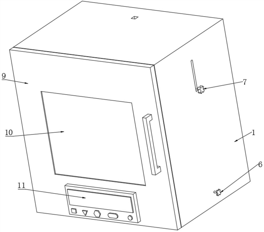
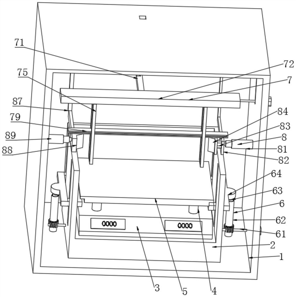
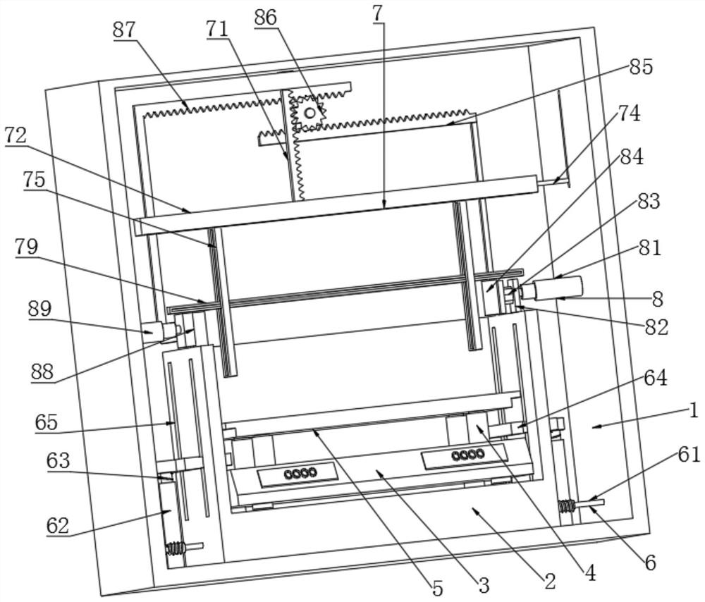
[0028] A multifunctional metal material detection device, comprising a detection box 1, a baffle plate 2 is fixedly connected to the bottom of the inner cavity of the detection box 1, an electronic scale 3 is fixedly connected to the bottom of the inner cavity of the baffle plate 2, and a sleeve is fixedly connected to the upper end of the electronic scale 3 4. The inner cavity of the sleeve 4 is slidingly connected with the tray 5. The inner cavity of the detection box 1 is installed with a lifting device 6 on both sides of the baffle 2. The inner cavity of the detection box 1 is installed with a measuring device 7 above the baffle 2. The detection box 1 Extrusion devices 8 are installed on both sides of the inner cavity wall, and the front end of the detection box 1 is connected to the box door 9 through hinge rotation. The middle part of the box door 9 is provided with an observation window 10, and one side of the box door 9 is located below the observation window 10. A cont...

Embodiment 2

[0029]Embodiment 2: The difference between this implementation and Embodiment 1 is that the extrusion device 8 consists of an electric telescopic rod 81, a mounting plate 82, a pressure sensor 83, a first extrusion plate 84, a first rack 85, and a transmission gear 86. , the second rack 87, the second extruding plate 88 and telescopic rod 89, one side of the cavity wall of the detection box 1 is fixedly connected with an electric telescopic rod 81, and one side of the electric telescopic rod 81 is fixedly connected with a mounting plate 82. One side of the mounting plate 82 is fixedly connected with a pressure sensor 83, one side of the pressure sensor 83 is fixedly connected with a first extrusion plate 84, one side of the mounting plate 82 is fixedly connected with a first rack 85, and the first rack 85 is connected to the transmission gear 86. Mesh connection. One side of the inner cavity wall of the detection box 1 is connected with a transmission gear 86 through a pin sha...


PUM


Abstract

A multifunctional metal material detection device disclosed by the present invention comprises a detection box, a baffle plate is fixedly connected to the bottom of an inner cavity of the detection box, an electronic scale is fixedly connected to the bottom of an inner cavity of the baffle plate, a sleeve is fixedly connected to the upper end face of the electronic scale, and a tray is slidably connected to an inner cavity of the sleeve. Lifting devices are installed at the positions, on the two sides of the baffle, of an inner cavity of the detection box, a measuring device is installed at the position, above the baffle, of the inner cavity of the detection box, extrusion devices are installed at the two sides of the wall of the inner cavity of the detection box, a box door is rotationally connected to the front end face of the detection box through hinges, and an observation window is formed in the middle of the box door; and a control panel is fixedly connected to one side of the box door and located below the observation window. The multifunctional metal material detection device solves the problem that a traditional metal material detection device is inconvenient to detect the weight and hardness of a material at the same time.

Description

technical field [0001] The invention relates to the technical field of metal material detection, in particular to a multifunctional metal material detection device. Background technique [0002] Metal material refers to the collective name of metal elements or materials with metal characteristics mainly composed of metal elements, including pure metals, alloys, intermetallic compounds of metal materials and special metal materials, among which iron, copper, aluminum and tin are common , nickel, gold, silver, lead, zinc, etc. Different metal materials need to be tested for their performance after processing and synthesis. The scope of metal material testing involves mechanical performance testing of ferrous metals, non-ferrous metals, mechanical equipment and parts, Chemical composition analysis, metallographic analysis, precision dimension measurement, non-destructive flaw detection, corrosion resistance test and environmental simulation test, etc. [0003] However, most of...

Claims


Application Information

Patent Timeline
Patent Type & Authority Applications(China)
IPC IPC(8): G01N3/08G01N3/42G01B5/02G01B5/06G01B5/28G01G19/00
CPCG01N3/08G01N3/42G01B5/02G01B5/061G01B5/28G01G19/00G01N2203/0003G01N2203/0019G01N2203/0076G01N2203/0676
Inventor 孙振才
Owner 苏州捭源金属材料科技有限公司
Learn More