Ceramic pressure flushing equipment and flushing method thereof
A technology of pressure and ceramics, which is applied in the field of ceramic pressure washing equipment and its washing, can solve the problems of poor flushing water boosting effect, less water sealing water utilization, and inability to significantly improve the flushing capacity, so as to increase the water volume and improve the effect Effect
- Summary
- Abstract
- Description
- Claims
- Application Information
AI Technical Summary
Problems solved by technology
Method used
Image
Examples
Embodiment 1
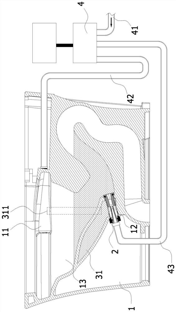
[0041] refer to Figure 1-11 As shown, wherein, the water replenishment structure 3 is built in the toilet cavity 1 .
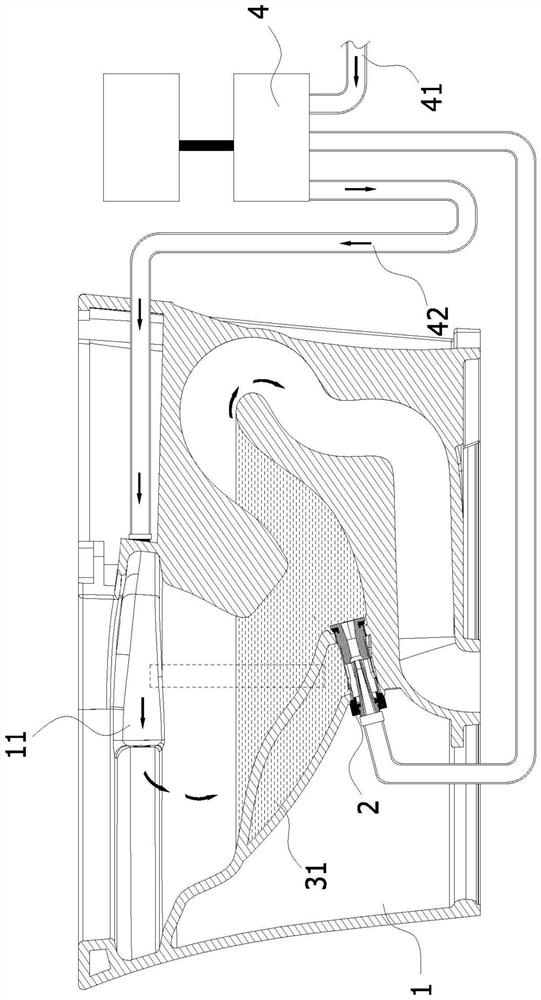
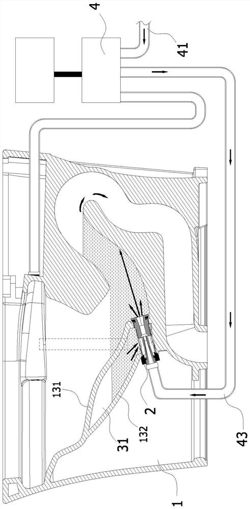
[0042] A ceramic pressure flushing device, comprising: a toilet cavity 1, since it is a jet-type siphon toilet, it has an upper flushing flow path and a lower flushing flow path, correspondingly, a lower flushing port needs to be set in the toilet cavity 1 12 and the upper flush port 11 are installed with the following spray brush nozzle 2 and the upper spray brush nozzle.
[0043] On the outside, in order to provide pressure water to the lower spray nozzle 2 and the upper spray nozzle, a pressure water control valve 4 needs to be provided, wherein the pressure water control valve 4 includes three flow paths, one of which is externally connected to the external pressure water. The input pipe 41, one way is the first output pipe 42 that is connected with the upper spray nozzle to provide the brush circle water flow, and the other way is the second output pipe...
Embodiment 2
[0062] The difference between this embodiment and Embodiment 1 is that: the water replenishing structure 3 is arranged outside the toilet cavity 1 .
[0063] In embodiment 1, it is specifically described that the water supply structure 3 is inside the toilet cavity 1, and the water supply method is to communicate with the water seal tank 13, and replenish water to the water supply chamber 31 at the same time when the water seal tank 13 is replenished.
[0064] refer to Figure 11 , and in this embodiment, the water supply structure 3 is an external mobile water tank 321, the mobile water tank 321 can be installed when in use, and removed when not in use, more flexible, wherein, the water outlet of the water tank 321 One end is connected to the water mixing hole 211 through a water supply pipe 322, and its water inlet end is connected to an external water source through a water supply pipe 323. There are two ways to replenish water for the water tank 321, one is to directly rep...
PUM
 Abstract
Description
Claims
Application Information
 - Generate Ideas
- Intellectual Property
- Life Sciences
- Materials
- Tech Scout
- Unparalleled Data Quality
- Higher Quality Content
- 60% Fewer Hallucinations
Browse by: Latest US Patents, China's latest patents, Technical Efficacy Thesaurus, Application Domain, Technology Topic, Popular Technical Reports.
© 2025 PatSnap. All rights reserved.Legal|Privacy policy|Modern Slavery Act Transparency Statement|Sitemap|About US| Contact US: help@patsnap.com


