Gas spark switch discharge experiment circuit and device
A technology of gas spark switch and experimental circuit, which is applied in the direction of testing dielectric strength, etc., can solve the problems of inability to provide discharge current waveform and low aging efficiency of the tested switch, so as to improve the efficiency of circuit construction, facilitate pulse shaping, and high aging efficiency Effect
- Summary
- Abstract
- Description
- Claims
- Application Information
AI Technical Summary
Problems solved by technology
Method used
Image

Examples
Embodiment 1
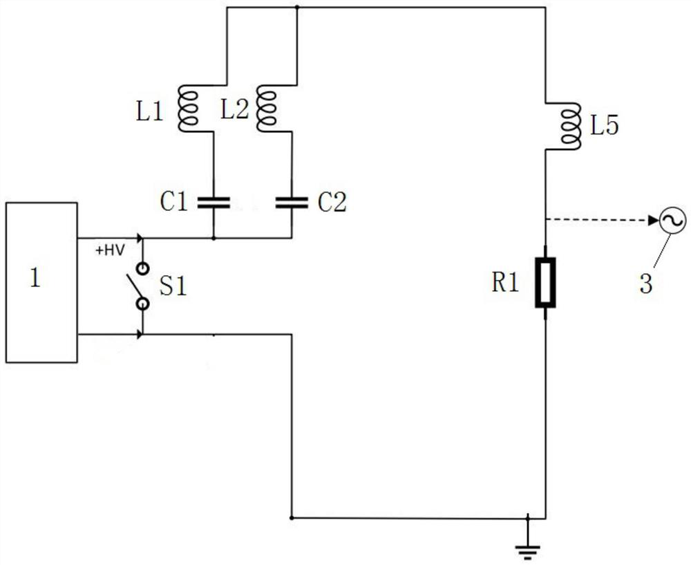
[0039] like Figure 1 to Figure 9 As shown, a gas spark switch discharge experimental circuit, including the test switch S1, the first pulse forming network, the inductor L 5 , resistance R 1 , one end of S1, the first pulse forming network, L 5 , R 1 , and the ground are electrically connected in turn, and the other end of S1 is electrically connected to the ground in turn, and the first pulse forming network includes N LC series branches connected in parallel with each other; wherein, N≥2 and N is an integer.
[0040] When in use, the gas spark switch discharge experimental circuit is electrically connected to the charging power source 1 and the measuring system 3 respectively. The circuit of the present invention provides high-quality waveforms for the discharge experiment of the tested switch S1, the waveform reverse current is very small, has a certain flat top, and is suitable for studying the electrode ablation problem of the switch, because the ablation of the elect...
Embodiment 2
[0056] like Figure 1 to Figure 9 As shown, as a further optimization of Embodiment 1, this embodiment includes all the technical features of Embodiment 1. In addition, this embodiment also includes the following technical features:
[0057] A gas spark switch discharge experimental device includes the gas spark switch discharge experimental circuit, and also includes a charging power source 1 and a measurement system 3 respectively electrically connected to the gas spark switch discharge experimental circuit.
[0058] The circuit of the present invention provides high-quality waveforms for the discharge experiment of the tested switch S1, the waveform reverse current is very small, has a certain flat top, and is suitable for studying the electrode ablation problem of the switch, because the ablation of the electrode is related to the direction of the current; The waveform provided by the inventive circuit is consistent with the actual working state of the switch, which can im...
Embodiment 3
[0064] like Figure 1 to Figure 9 As shown, this embodiment includes all the technical features of Embodiment 1 and Embodiment 2. On the basis of Embodiment 1 and Embodiment 2, this embodiment provides a more detailed implementation mode.
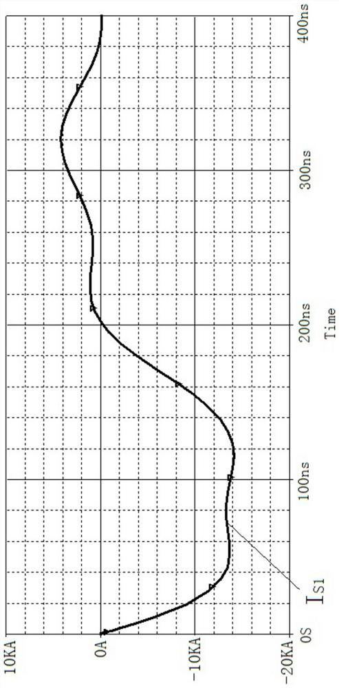
[0065] There is room for improvement in the current switch discharge experimental circuit. The waveform of the discharge current should preferably be consistent with the actual working state, that is, a square wave with a certain flat top, no oscillation, and no reverse current; the peak value of the current should reach more than 10 kA; it can be modulated according to actual needs the pulse width.
[0066] In order to achieve this purpose, the present invention invented a discharge experiment circuit, and developed the corresponding experiment device.
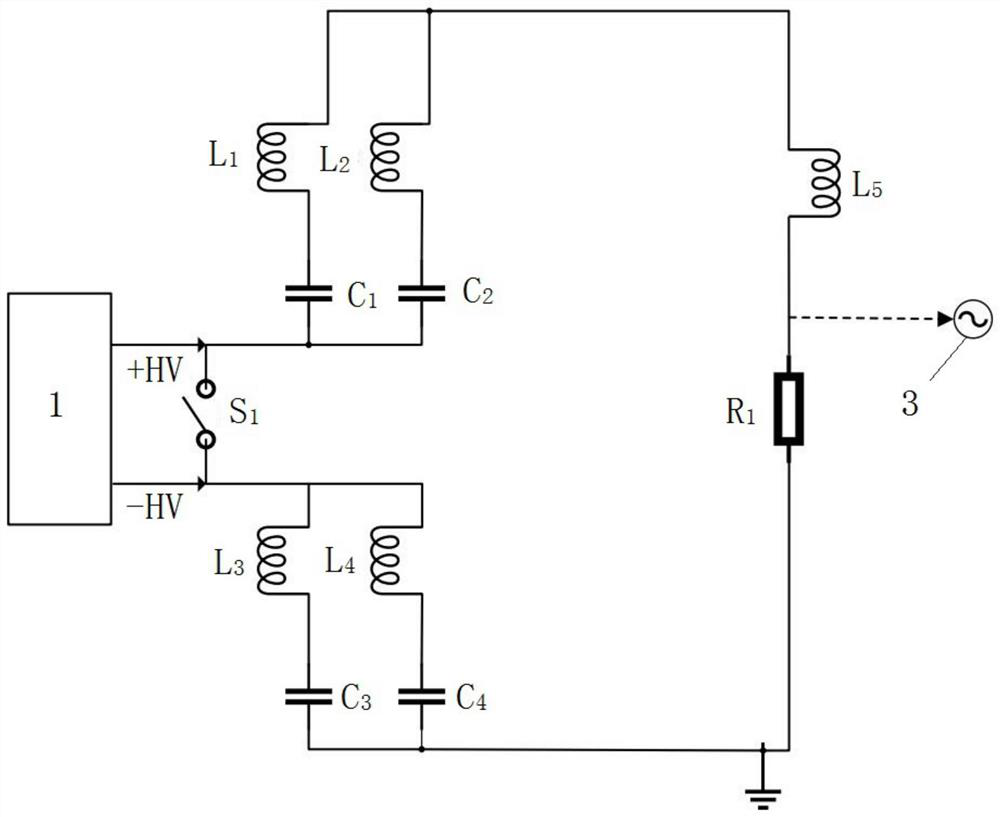
[0067] The experimental circuit designed as figure 2 shown.
[0068] The whole experimental system can be divided into three parts: power supply, discharge circuit and measurement sys...
PUM
 Abstract
Description
Claims
Application Information
 - Generate Ideas
- Intellectual Property
- Life Sciences
- Materials
- Tech Scout
- Unparalleled Data Quality
- Higher Quality Content
- 60% Fewer Hallucinations
Browse by: Latest US Patents, China's latest patents, Technical Efficacy Thesaurus, Application Domain, Technology Topic, Popular Technical Reports.
© 2025 PatSnap. All rights reserved.Legal|Privacy policy|Modern Slavery Act Transparency Statement|Sitemap|About US| Contact US: help@patsnap.com