
Automatic aging-detection equipment

A detection equipment and automatic technology, which is applied in the direction of measuring electricity, measuring devices, and measuring electrical variables, etc., can solve the problems of aging significance discount, waste of economy and site utilization, and large occupied volume of on-load aging equipment to achieve improvement Quality, life extension effect

Pending Publication Date: 2018-11-06
WUHAN SOUTH SAGITTARIUS INTEGRATION CO LTD
View PDF0 Cites 2 Cited by
  • Summary
  • Abstract
  • Description
  • Claims
  • Application Information

AI Technical Summary

Problems solved by technology

[0002] At present, the aging of module products is mostly placed in a high-temperature box for direct heating and baking, and the driver chip that needs to be verified by high temperature does not work at high temperature with load, so the significance of aging is greatly reduced; and the existing modules Most of the aging equipment is to realize the aging of a single product, and it is necessary to repurchase or make aging equipment when replacing the product
Moreover, the on-load burn-in equipment takes up a large volume, which causes relatively large waste in terms of economy and site utilization. At the same time, the existing module-type burn-in equipment cannot realize real-time monitoring of the modules to be tested during the burn-in process, and there is no high temperature on the device. The impact of accurate data information

Method used


Image

  • Automatic aging-detection equipment
  • Automatic aging-detection equipment
  • Automatic aging-detection equipment

Examples


Embodiment Construction

[0036] The principles and features of the present invention are described below in conjunction with the accompanying drawings, and the examples given are only used to explain the present invention, and are not intended to limit the scope of the present invention.

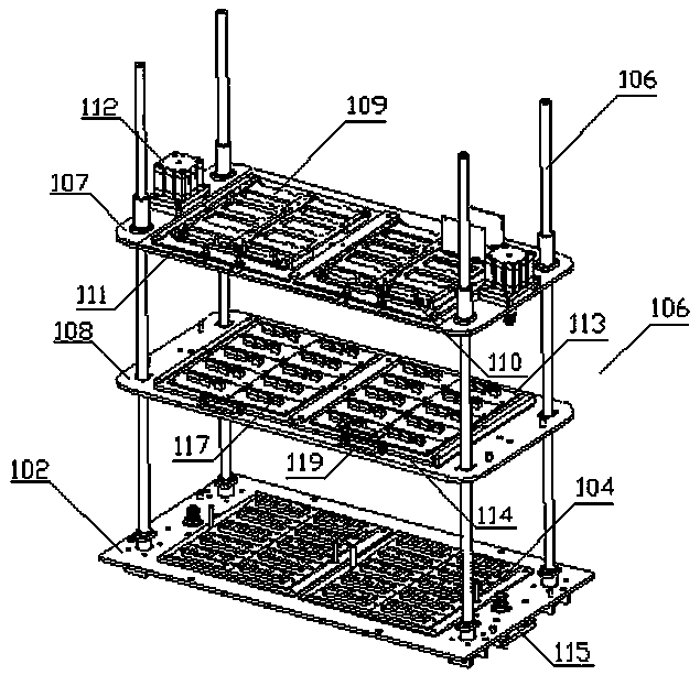
[0037] Such as Figure 1-4 As shown, an automatic aging detection device includes a main control cabinet, a load cabinet and a test cabinet, a plurality of modules to be tested are arranged in the test cabinet, a multi-path load is arranged in the load cabinet, and the multi-path load It is electrically connected to the modules to be tested one by one. The main control cabinet is equipped with an industrial computer, a relay control circuit and a CAN communication module. The industrial computer is electrically connected to the relay control circuit. The test modules are electrically connected, and all the modules to be tested are electrically connected to the industrial computer through the CAN communication module...


PUM


Abstract

The invention relates to automatic aging-detection equipment which comprises a main control cabinet, a load cabinet and a test cabinet, wherein a plurality of modules to be tested are arranged in thetest cabinet; paths of loads are arranged in the load cabinet; the loads are electrically connected with the modules to be tested in a one-to-one correspondence manner; an industrial control computer,a relay control circuit and a CAN (Controller Network Area) communication module are arranged in the main control cabinet; the industrial control computer is electrically connected with the relay control circuit; the relay control circuit is electrically connected with all the modules to be tested; and all the modules to be tested are electrically connected with the industrial control computer through the CAN communication module. The automatic aging-detection equipment disclosed by the invention can effectively detect working state information of the modules to be tested in a loaded state, and parameter information such as working current acquired by the modules to be tested is fed back to the industrial control computer through a CAN bus, so that the industrial control computer precisely monitors the parameter information such as the working current of the modules to be tested in an aging process in real time and provides a basis for management and control of quality improvement, and the automatic-aging detection equipment is favorable for improving the quality of a product.

Description

technical field [0001] The invention relates to the technical field of automatic detection, in particular to an automatic aging detection device. Background technique [0002] At present, the aging of module products is mostly placed in a high-temperature box for direct heating and baking, and the driver chip that needs to be verified by high temperature does not work at high temperature with load, so the significance of aging is greatly reduced; and, the existing modules Most of the similar aging equipment is to realize the aging of a single product, and it is necessary to repurchase or manufacture aging equipment when replacing a product. Moreover, the on-load aging equipment occupies a large volume, which causes a relatively large waste in terms of economy and site utilization. At the same time, the existing module aging equipment cannot realize real-time monitoring of the modules to be tested during the aging process, and there is no high temperature on the device. The ...

Claims


Application Information

Patent Timeline
Patent Type & Authority Applications(China)
IPC IPC(8): G01R31/00
CPCG01R31/00
Inventor 叶聪陈星熊济方汪绍文石宏黄诗郁莹徽许锐黄思远
Owner WUHAN SOUTH SAGITTARIUS INTEGRATION CO LTD
Learn More