Fuel pretreatment device and fuel cell system
A fuel and material technology, applied in the field of fuel pretreatment devices and fuel cell systems, can solve problems such as overheating or undercooling, carrier destruction of reactant conversion rate, catalyst sintering, etc.
- Summary
- Abstract
- Description
- Claims
- Application Information
AI Technical Summary
Problems solved by technology
Method used
Image

Examples
Embodiment 1
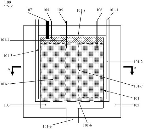
[0096] Such as figure 1 As shown, in this embodiment, the fuel pretreatment device 100 includes a reaction chamber 101 and an insulation layer 102. The reaction chamber 101 is an integrated reactor, and the insulation layer 102 is coated on the outside of the reaction chamber 101, and is completely or large The reaction cavity 101 is partially covered. The endothermic and exothermic fuel pretreatment reactions are carried out synchronously in the reaction chamber 101, and both generate hydrogen-rich fuel required for downstream power generation. The fuel pretreatment reactions are but not limited to endothermic ammonia decomposition reactions and exothermic alkanes The thermal self-sustaining composite reaction of partial oxidation reforming reaction mixture has the characteristics of thermoneutral or slightly exothermic.
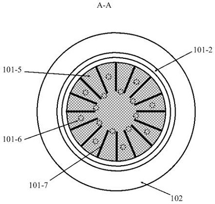
[0097] Such as figure 2 As shown, the reaction chamber 101 and the insulation layer 102 can be designed in the form of concentric cylinders. Further de...
Embodiment 2
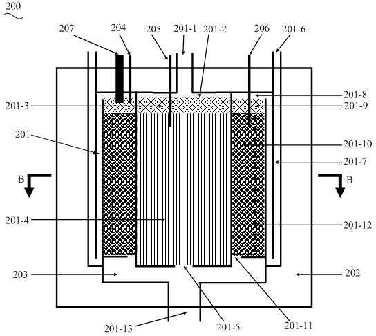
[0104] Such as image 3 As shown, the same as the first embodiment, the fuel pretreatment device 200 also includes a reaction chamber 201 and an insulating layer 202, the reaction chamber 201 is an integrated reactor, and the insulating layer 202 is coated on the outside of the reaction chamber 201 , and completely or mostly cover the reaction cavity 201 . The difference is that the reaction chamber 201 includes a first sub-cavity and a second sub-cavity, the second sub-cavity is sleeved outside the first sub-cavity, and between the first sub-cavity and the second sub-cavity isolated from each other. The first sub-cavity is used for inputting the materials to be reacted for the exothermic reaction or the materials to be reacted for the endothermic reaction, and the second sub-cavity is used for inputting the materials to be reacted for the endothermic reaction or the materials to be reacted for the exothermic reaction.
[0105] The number of the first sub-cavity and the seco...
Embodiment 3
[0118] refer to Figure 8 and Figure 9, the fuel pretreatment device 300 provided in this embodiment is similar to the structure in the second embodiment. The fuel pretreatment device 300 also includes a reaction chamber 301 and an insulating layer 302. The reaction chamber 301 is an integrated reactor, and the heat preservation The layer 302 covers the outside of the reaction chamber 301, and completely or mostly covers the reactor, wherein the inner area starts from the material inlet 301-1 of the inner reaction chamber, and the ammonia gas in the material to be reacted from the outside flows into it. device, and then flows down into the cylindrical inner reaction chamber inlet area 301-2 directly connected with the inner reaction chamber material inlet 301-1, and reacts there. The internal reaction chamber mainly includes two sections: the internal reaction chamber material distribution area 301-3 near the inlet side and the internal catalytic reaction area 301-4 near the...
PUM
 Abstract
Description
Claims
Application Information
 - R&D
- Intellectual Property
- Life Sciences
- Materials
- Tech Scout
- Unparalleled Data Quality
- Higher Quality Content
- 60% Fewer Hallucinations
Browse by: Latest US Patents, China's latest patents, Technical Efficacy Thesaurus, Application Domain, Technology Topic, Popular Technical Reports.
© 2025 PatSnap. All rights reserved.Legal|Privacy policy|Modern Slavery Act Transparency Statement|Sitemap|About US| Contact US: help@patsnap.com