


Quick Research
Generate reliable direction feasibility study reports for your R&D in just a few steps.

Technical Q&A
Discover and master advanced knowledge NOW. Basics, ideas, possibilities, all at once.

Find Solutions
As an expert in R&D theories, this can generate solutions to your technical problems instantly.

Evaluate Feasibility
Analyze your overall solution with one click, know your potential R&D risks in advance.

Monitor Landscape
Get weekly tech updates, stay abreast of the latest tech innovations and key insights.
Fuel pretreatment device and fuel cell system
一种燃料、物料的技术,应用在燃料前处理装置及燃料电池系统领域,能够解决催化剂烧结、过热或过冷、不均匀温度分布等问题
- Summary
- Abstract
- Description
- Claims
- Application Information
AI Technical Summary
Problems solved by technology
Method used
Image


Examples
Embodiment 1
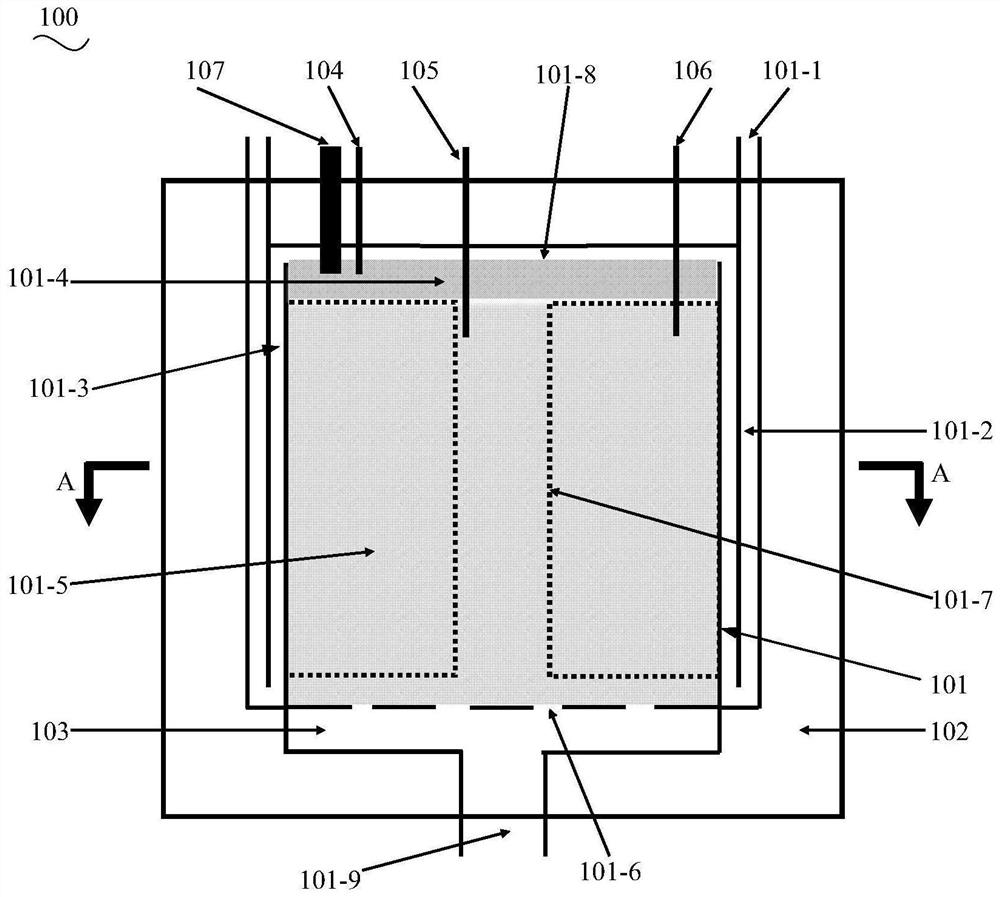
[0097] like figure 1 As shown, in this embodiment, the fuel pretreatment device 100 includes a reaction chamber 101 and an insulating layer 102, the reaction chamber 101 is an integrated reactor, and the insulating layer 102 covers the reaction chamber 101 and is completely or large The reaction chamber 101 is partially covered. The endothermic and exothermic fuel pretreatment reactions are simultaneously performed in the reaction chamber 101, and both generate hydrogen-rich fuel required for downstream power generation. The fuel pretreatment reactions are but are not limited to endothermic ammonia decomposition reactions and exothermic alkanes. The partial oxidation reforming reaction is a self-sustaining composite reaction of heat mixing, which is thermally neutral or slightly exothermic.
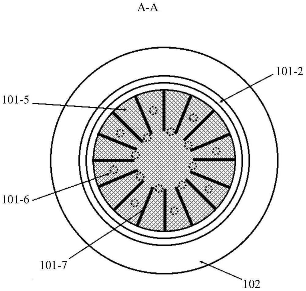
[0098] like figure 2 As shown, the reaction chamber 101 and the thermal insulation layer 102 can be designed in the form of concentric cylinders. Further introduction will be given be...
Embodiment 2
[0105] like image 3 As shown, the same as the first embodiment, the fuel pretreatment device 200 also includes a reaction chamber 201 and an insulating layer 202 , the reaction chamber 201 is an integrated reactor, and the insulating layer 202 covers the outside of the reaction chamber 201 , and completely or mostly cover the reaction chamber 201 . The difference is that the reaction chamber 201 includes a first sub-chamber and a second sub-chamber, the second sub-chamber is sleeved outside the first sub-chamber, and between the first sub-chamber and the second sub-chamber Set isolated from each other. The first sub-cavity is used for inputting the material to be reacted for exothermic reaction or the material to be reacted for endothermic reaction, and the second sub-cavity is used for inputting the material to be reacted for endothermic reaction or the material to be reacted for exothermic reaction.
[0106] The number of the first sub-cavity and the second sub-cavity is ...
Embodiment 3
[0119] refer to Figure 8 and Figure 9, the fuel pretreatment device 300 provided in this embodiment is similar in structure to the second embodiment. The fuel pretreatment device 300 also includes a reaction chamber 301 and a thermal insulation layer 302. The reaction chamber 301 is an integrated reactor, and the thermal insulation The layer 302 covers the outside of the reaction chamber 301 and completely or mostly covers the reactor, wherein the inner region starts from the material inlet 301-1 of the inner reaction chamber, and the ammonia gas in the material to be reacted input from the outside flows into this device, and then flows downward into the cylindrical inner reaction chamber inlet area 301-2 directly communicating with the inner reaction chamber material inlet 301-1, and reacts there. The inner reaction chamber mainly includes two sections: the inner reaction chamber material distribution zone 301-3 near the inlet side and the inner catalytic reaction zone 301...
PUM
 Abstract
Description
Claims
Application Information
 - R&D Engineer
- R&D Manager
- IP Professional
- Industry Leading Data Capabilities
- Powerful AI technology
- Patent DNA Extraction
Browse by: Latest US Patents, China's latest patents, Technical Efficacy Thesaurus, Application Domain, Technology Topic, Popular Technical Reports.
© 2024 PatSnap. All rights reserved.Legal|Privacy policy|Modern Slavery Act Transparency Statement|Sitemap|About US| Contact US: help@patsnap.com