Cone beam computed tomography imaging method and system based on scattering recognition

A technology of tomography and imaging methods, which is applied in the field of image processing, can solve problems such as complex signal composition, and achieve the effect of reducing estimation errors

Active Publication Date: 2022-04-26
康达洲际医疗器械有限公司
View PDF19 Cites 2 Cited by
  • Summary
  • Abstract
  • Description
  • Claims
  • Application Information

AI Technical Summary

Problems solved by technology

Its main challenge is that the obtained signal contains both scattered rays and primary rays, which is not necessarily suitable for estimating the real scattered rays due to the complexity of the signal composition

Method used


Image

  • Cone beam computed tomography imaging method and system based on scattering recognition
  • Cone beam computed tomography imaging method and system based on scattering recognition
  • Cone beam computed tomography imaging method and system based on scattering recognition

Examples


Embodiment 1

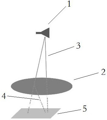
[0047] In traditional CBCT, such as image 3 As shown, there is only one flat panel detector (FPD) as the original ray detector of CBCT. Among them, FPD is a two-dimensional original ray detector, which has position sensitivity after discretization. The raw rays 3 generated by the emitter 1 are transmitted and projected onto the FPD 5, whose ray intensities are recorded as shadows. By repeating the original radiography around the target tissue 2 and recording it at different angles, a cross-sectional image of the target tissue can be reconstructed. However, the original rays generate scattered rays4 in the target tissue, which in turn contaminates the data acquired by FPD. Then use various scattered ray estimation algorithms to estimate the scattered rays, but the estimation in this process can basically only use the polluted data obtained on the FPD.

[0048] Among them, one of the classic algorithms of the scattered ray estimation algorithm is filter convolution, in which...

Embodiment 2

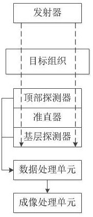
[0103] In order to better understand the technical content of the present invention, this embodiment illustrates the present invention by way of system structure, as figure 2 As shown, a cone-beam computed tomography imaging system based on scatter recognition, including:

[0104] A transmitter for emitting raw rays with a preset frequency spectrum width to target tissue;

[0105] The top detector is used to obtain the first ray intensity of the original ray at each pixel point after penetrating the target tissue;

[0106] The collimator is used to attenuate the scattered rays after the original rays penetrate through the target tissue and the top detector;

[0107] The base detector is used to obtain the second ray intensity at each pixel of the original ray after being scattered and attenuated by the collimator;

[0108] The data processing unit is configured to estimate the scattered ray intensity after the original ray penetrates the target tissue according to the first...


PUM


Abstract

The invention discloses a cone-beam computed tomography imaging method based on scattering recognition, which relates to the technical field of image processing and comprises the following steps: controlling an emitter to emit transmission rays with a preset spectral width to a target tissue; acquiring the first ray intensity of the transmission ray at each pixel point after penetrating through the target tissue through a top detector; acquiring second ray intensity of the transmission ray at each pixel point after scattering attenuation of the collimator through a base layer detector; according to the first ray intensity and the second ray intensity at the corresponding pixel points, estimating the scattered ray intensity after the transmission ray penetrates through the target tissue; on the basis of the estimated scattered ray intensity, estimating primary ray intensity after the scattered rays are removed through the second ray intensity; and constructing tomography imaging of the target tissue according to the initial ray intensity at each pixel point. According to the invention, the imaging result can be obtained more quickly under the condition of ensuring the safety of the irradiation dose.

Description

technical field [0001] The invention relates to the technical field of image processing, in particular to a cone beam computed tomography imaging method and system based on scattering recognition. Background technique [0002] Cone beam computed tomography (CBCT) is an imaging method widely used in the study of tissue structure, such as image-guided targeted release and radiation guidance. Through the application of this technology on the C-arm, it provides good clinical imaging capabilities and mobility for the study of the target tissue structure, and it is easier to approach the target tissue, which strongly supports operations such as stent or stent placement in the target tissue implementation. [0003] However, due to the wide coverage of the cone beam and detectors of CBCT, when the radiation (X-rays) penetrates the target tissue, the radiation in the target tissue and equipment will be severely scattered and detected by the detector. However, a high scattered photo...

Claims


Application Information

Patent Timeline
IPC IPC(8): G06T11/00G01N23/046
CPCG06T11/005G01N23/046
Inventor 小野光吉振宁郭咏梅郭咏阳
Owner 康达洲际医疗器械有限公司
Why Eureka
Try Eureka