
Atmospheric interference phase correction method for ground-based arc interference synthetic aperture radar

A technology of interferometric synthetic aperture and atmospheric interference, applied in the field of surveying and mapping science, can solve the problem of low accuracy of external data at the same time, and achieve the effect of good correction effect, strong adaptability and robustness

Pending Publication Date: 2022-04-26
宋千 +1
View PDF0 Cites 3 Cited by
  • Summary
  • Abstract
  • Description
  • Claims
  • Application Information

AI Technical Summary

Problems solved by technology

[0005] Aiming at the deficiencies in the prior art, the purpose of the present invention is to provide a ground-based circular-arc interference synthetic aperture radar atmospheric interference phase correction method to solve the need to introduce external data in the ground-based circular-arc interference synthetic aperture radar atmospheric interference phase correction method in the prior art At the same time, the problem of low accuracy

Method used


Image

  • Atmospheric interference phase correction method for ground-based arc interference synthetic aperture radar
  • Atmospheric interference phase correction method for ground-based arc interference synthetic aperture radar
  • Atmospheric interference phase correction method for ground-based arc interference synthetic aperture radar

Examples


Embodiment Construction

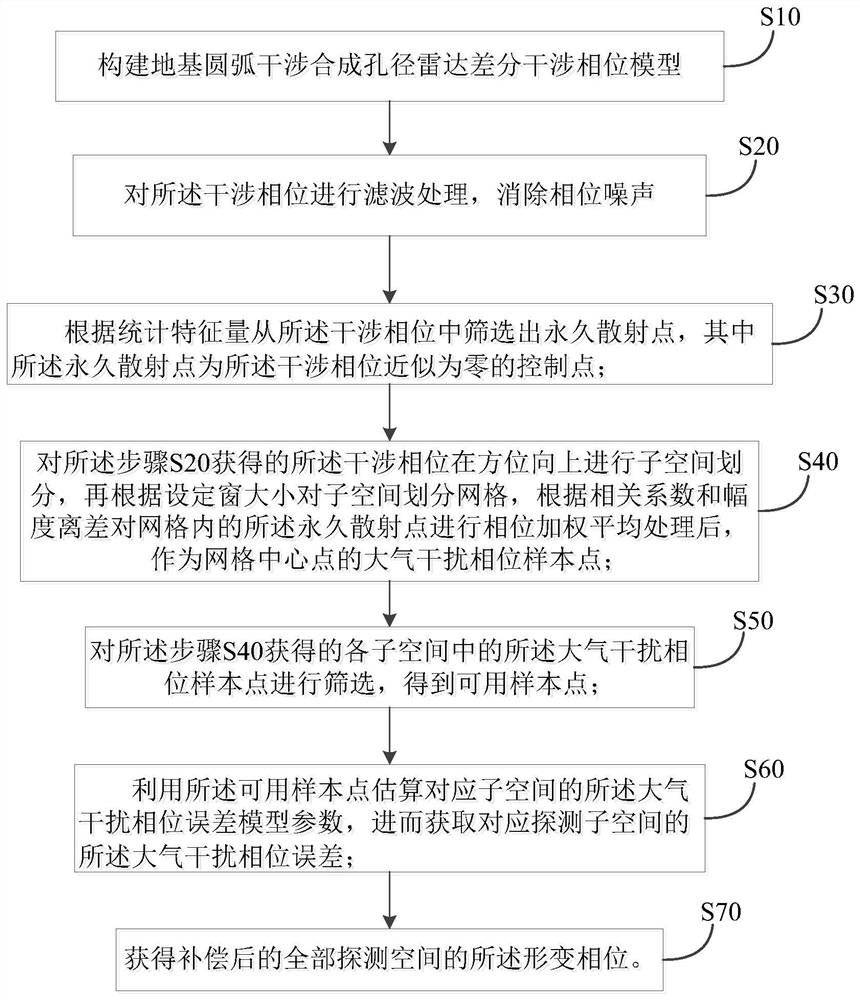
[0063] In order to facilitate the understanding of the present invention, the present invention will be described more fully below with reference to the associated drawings. Preferred embodiments of the invention are shown in the accompanying drawings. However, the present invention can be embodied in many different forms and is not limited to the embodiments described herein. On the contrary, these embodiments are provided to make the understanding of the disclosure of the present invention more thorough and comprehensive.

[0064] Unless otherwise defined, all technical and scientific terms used herein have the same meaning as commonly understood by one of ordinary skill in the technical field of the invention. The terms used herein in the description of the present invention are for the purpose of describing specific embodiments only, and are not intended to limit the present invention.

[0065] Such as figure 1 Shown is a flow chart of a ground-based circular-arc interf...


PUM


Abstract

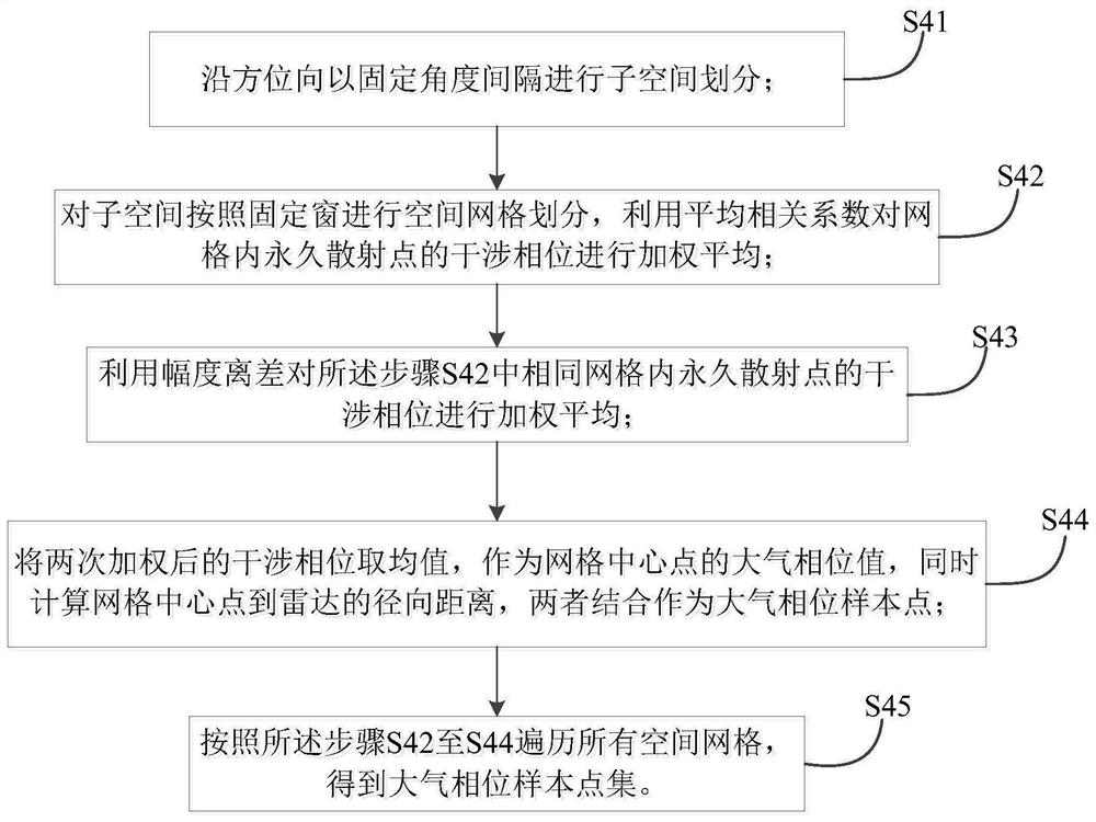
The invention is suitable for the technical field of surveying and mapping science, and relates to a foundation arc interference synthetic aperture radar atmospheric interference phase correction method comprising the following steps: constructing a foundation arc interference synthetic aperture radar differential interference phase model; eliminating phase noise; screening permanent scattering points; subspace division is carried out on the obtained interference phase in the azimuth direction, grid division is carried out on the subspace according to the size of a set window, phase weighted average processing is carried out on permanent scattering points in a grid according to a correlation coefficient and amplitude deviation, and the processed permanent scattering points serve as atmospheric interference phase sample points of a grid center point; screening the obtained atmospheric interference phase sample points to obtain available sample points; using the available sample points to estimate atmospheric interference phase error model parameters, and then obtaining the atmospheric interference phase error of the detection area; and the deformation phase is obtained. The method is simple and efficient, external auxiliary data does not need to be introduced, the atmospheric interference phase is corrected only by depending on the interference phase, and the method has high correction precision.

Description

technical field [0001] The invention belongs to the field of surveying and mapping science and technology, and in particular relates to a ground-based circular-arc interference synthetic aperture radar atmospheric interference phase correction method. Background technique [0002] SAR (Synthetic Aperture Radar), as an all-day, all-weather, high-resolution imaging radar, is widely used in the field of remote sensing. Since the SAR image has phase information, the non-contact and high-precision extraction of the deformation information of the imaging area can be realized through the interference processing of the SAR image sequence. In view of the above advantages of the SAR system, it has become one of the important means of ground deformation monitoring. one. Traditional SAR is mostly carried on platforms such as satellites and aircraft, which makes the radar revisit time very long and cannot continuously monitor specific targets. Ground-Based SAR (Ground Based SAR, GBSAR)...

Claims


Application Information

Patent Timeline
Patent Type & Authority Applications(China)
IPC IPC(8): G01S7/40G01S13/90
CPCG01S7/40G01S13/9023
Inventor 王鹏宇宋千
Owner 宋千
Learn More