
Optical fiber pulse laser oscillator and oscillation starting method

A pulsed laser and oscillator technology, which is applied to the structure/shape of lasers, laser components, and optical resonators, can solve problems such as inability to self-start, inconvenient use, complex optical path structure, etc., and achieve the effect of not being able to self-start

Pending Publication Date: 2022-04-22
NAT UNIV OF DEFENSE TECH
View PDF7 Cites 0 Cited by
  • Summary
  • Abstract
  • Description
  • Claims
  • Application Information

AI Technical Summary

Problems solved by technology

However, the existing technology usually requires two-stage optical path cascading to achieve spectral broadening and dislocation filtering. There are two gain fibers and pumps, the system is complex, and it cannot be self-started like other passive mode-locked fiber lasers. Usually, it needs Laser oscillation is achieved by external injection of seed laser or by manually adjusting the auxiliary space optical path to introduce disturbance, which brings inconvenience to the use
[0005] In the prior art, the ultrafast laser oscillator system based on spectral broadening and dislocation filtering effects has a complex optical path structure and cannot be self-started. No effective solution has been proposed yet.

Method used


Image

  • Optical fiber pulse laser oscillator and oscillation starting method
  • Optical fiber pulse laser oscillator and oscillation starting method
  • Optical fiber pulse laser oscillator and oscillation starting method

Examples


Embodiment Construction

[0029] The present invention will be further described below in conjunction with the accompanying drawings and specific embodiments. Terms such as "upper", "lower", "left", "right", "middle" and "one" quoted in the preferred embodiment are only for convenience of description, and are not used to limit the scope of the present invention. The scope of implementation and the change or adjustment of its relative relationship shall also be regarded as the scope of implementation of the present invention without substantive changes in technical content.

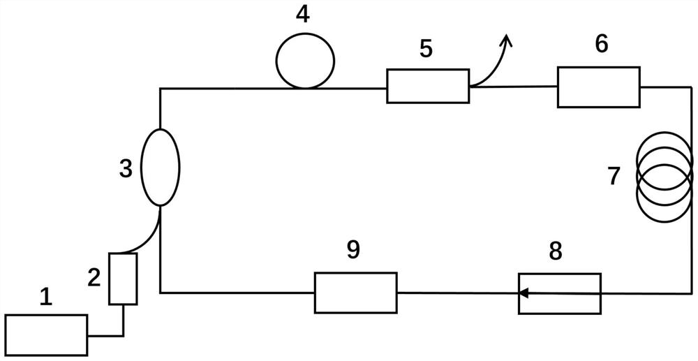
[0030] Such as figure 1 As shown, the invention provides a fiber pulse laser oscillator, comprising:

[0031] A pump laser 1, used to send out a pump signal;

[0032] The pumping optical modulator 2 modulates the pumping signal and outputs a pulsed pumping signal;

[0033] The beam combiner 3, the doped gain fiber 4, the coupler 5, the first filter 6, the passive fiber 7, the isolator 8, and the second filter 9 are sequentially ...


PUM

PropertyMeasurementUnit
lengthaaaaaaaaaa

Abstract

The invention discloses an optical fiber pulse laser oscillator and an oscillation starting method, and the oscillator comprises a pump laser which is used for transmitting a pump signal; the pump light modulator is used for modulating the pump signal and outputting a pulse pump signal; the beam combiner, the gain optical fiber, the coupler, the first filter, the passive optical fiber, the isolator and the second filter are sequentially connected to form a closed loop, the output end of the pump light modulator is connected with one input end of the beam combiner, a pulse pump signal is guided into the closed loop, the pulse pump signal can introduce disturbance to the whole closed loop, and then the whole closed loop is output. And the self-starting of the laser oscillator is realized. Wherein the second filter and the first filter have different central wavelengths, so that staggered filtering is realized, and direct current and weak pulse signals in a closed loop are inhibited. According to the invention, high-energy pulse laser can be realized, the problem that the oscillator cannot be self-started is solved, and the structure is more compact compared with the previous two-stage broadening and filtering.

Description

technical field [0001] The invention relates to the technical field of fiber laser oscillators, in particular to a fiber pulse laser oscillator and an oscillation starting method based on spectrum broadening and dislocation filtering effects. Background technique [0002] Ultrafast fiber lasers have broad applications in diverse fields such as advanced manufacturing, nonlinear optics, biomedical imaging, and laser micromachining. Compared with traditional solid-state lasers, fiber lasers have the advantages of compact system, maintenance-free, strong anti-interference ability, good heat dissipation, and good beam quality. Ultrafast fiber lasers with picosecond and femtosecond pulse widths have attracted considerable attention in the past decade. [0003] Passively mode-locked fiber lasers usually rely on the use of saturable absorber materials (such as semiconductor saturable absorbers, carbon nanotubes, graphene, black phosphorus, etc.) or equivalent saturable absorbers (s...

Claims


Application Information

Patent Timeline
Patent Type & Authority Applications(China)
IPC IPC(8): H01S3/067H01S3/08H01S3/094
CPCH01S3/06708H01S3/08013H01S3/08027H01S3/094003
Inventor 李灿王涛任博吴坚粟荣涛马鹏飞周朴
Owner NAT UNIV OF DEFENSE TECH
Learn More