
High-performance swept-frequency fiber laser

A fiber laser, high-performance technology, applied in the direction of lasers, laser components, phonon exciters, etc., can solve the problems of frequency sweep speed dependence, slow frequency sweep speed, long delay line loss, etc., and achieve instantaneous line width narrowing , Sweeping speed increased, good filtering effect

Pending Publication Date: 2020-01-17
SHENZHEN TECH UNIV
View PDF1 Cites 0 Cited by
  • Summary
  • Abstract
  • Description
  • Claims
  • Application Information

AI Technical Summary

Problems solved by technology

[0003] In the current technology, short-cavity frequency-sweeping lasers have the problems of slow frequency-sweeping speed and low reuse rate of devices
Fourier-domain film-locked frequency-sweeping lasers have a huge structure and require extremely long delay lines to increase the frequency-sweeping speed. At the same time, long delay lines bring great loss, making miniaturization and productization difficult, and the frequency-sweeping parameters are not very good. to optimize
The frequency-sweeping laser tuned by the grating polygon mirror has a frequency-sweeping speed that depends on the mechanical structure of the driving polygon mirror. It is difficult to increase the speed, it is difficult to adjust the optical path, and it is difficult to guarantee the stability of the output laser.

Method used


Image

  • High-performance swept-frequency fiber laser

Examples


Embodiment 1

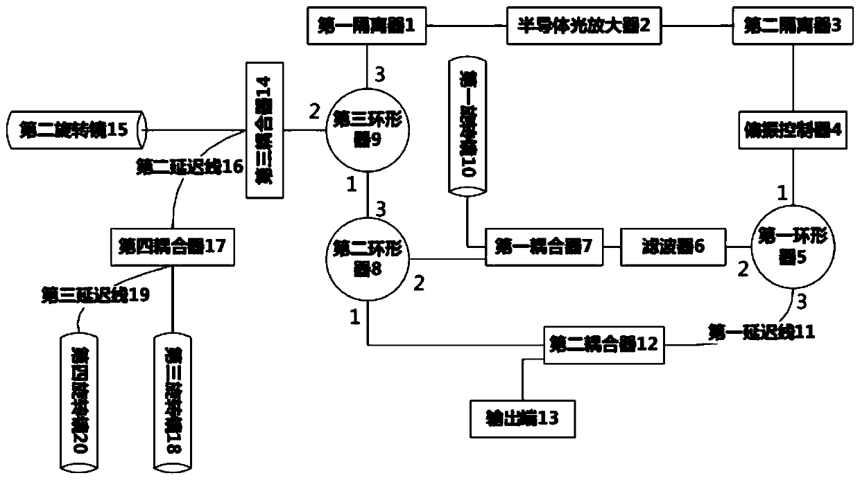
[0023] When the optical signal is output through the third pin of the first circulator 5, in order to achieve a better frequency sweeping effect, the optical signal can be further filtered, and the first delay can be connected to the third pin of the first circulator 5. Line 11 and second coupler 12.

[0024] Specifically, the first leg of the first delay line 11 described above is connected to the third leg of the first circulator 5, the second leg of the first delay line 11 is connected to the first leg of the second coupler 12, and the second coupling The second pin of the device 12 is connected to the first pin of the second circulator 8 to form a second path of the optical signal. That is, the twice-filtered optical signal output by the third pin of the first circulator 5 passes through the first delay line 11, the second coupler 12, the first pin of the second circulator 8, and the second pin of the second circulator 8. Feet, the first coupler 7, the filter 6, and the seco...

Embodiment 2

[0026] In order to further increase the frequency sweep speed of the optical signal and improve the performance of the frequency sweep laser, a frequency sweep doubling component can be installed on the above-mentioned optical path.

[0027] Specifically, the frequency sweep doubling component described above includes a third coupler 14, a second rotating mirror 15, a second delay line 16 and a third rotating mirror 18. The first leg of the third coupler 14 is connected to the second leg of the third circulator 9, the second leg of the third coupler 9 is connected to the second rotating mirror 15, and the second leg of the third coupler 14 is connected to the second delay line The first pin of 16 and the second pin of the second delay line 16 are connected to the third rotating mirror 18. It can be seen from the above that the optical signal can enter the third coupler 14 through the second leg of the third circulator 9, enter the second rotating mirror 15 through the second leg ...

Embodiment 3

[0030] In actual work, in order to ensure that the high-performance swept fiber laser described above can work stably for a long time and prevent the laser from being interrupted due to the influence of external temperature or current, the high-performance swept laser can be placed in a temperature and current controllable Environment.

[0031] Specifically, the semiconductor optical amplifier 2 in the above-mentioned high-performance swept laser is connected to a constant current drive circuit and a temperature control circuit. In order to ensure that the semiconductor optical amplifier 2 continuously and stably output the spontaneous radiation background light under the constant temperature state, the laser output will not be interrupted due to the long running time and high temperature. The constant current drive circuit and the temperature control circuit are disclosed in the Chinese patent application number 201821765806.X and the utility model patent titled "a laser light s...


PUM


Abstract

The invention provides a high-performance swept-frequency fiber laser. The high-performance swept-frequency fiber laser comprises a semiconductor optical amplifier, a first isolator, a second isolator, a polarization controller, a filter, a first coupler, a first circulator, a second circulator, a third circulator and a first rotating mirror. An optical signal reaches the first rotating mirror after being acted by the filter, and passes through the filter again after being reflected by the first rotating mirror, so the same optical signal can obtain a better filtering effect after being filtered twice. A first delay line and a second coupler are added in the optical path to form the second path, and the optical signal can pass through the filter again to achieve a multiple filtering effect. The optical channel is provided with a frequency sweep doubling assembly, so that the frequency sweep speed can be improved by multiple times. The semiconductor optical amplifier is connected with aconstant current driving circuit and a temperature control circuit, so that the semiconductor optical amplifier is ensured to continuously and stably output spontaneous radiation background light, and laser output is not interrupted due to long operation time and over-high temperature, therefore the stability of the whole system is improved.

Description

Technical field [0001] The invention relates to the field of fiber lasers, in particular to a high-performance frequency swept fiber laser. Background technique [0002] Optical coherence tomography can "non-invasively" obtain the internal structure of biological tissues, and the swept laser is the core component of the new generation of optical coherence tomography. The output parameters of the frequency sweep laser directly determine the effect of optical coherence tomography. Fiber-optic biomedical sensing technology combines fiber-optic sensing technology with biomedical detection technology to realize real-time detection in vivo. The time-domain information output by the swept laser can be directly displayed, which greatly improves the detection efficiency and resolution, and can give accurate detection results of cells, making it one of the best lasers for biomedical sensing. [0003] In the current technology, short-cavity swept lasers have the problems of slow sweep speed...

Claims


Application Information

Patent Timeline
Patent Type & Authority Applications(China)
IPC IPC(8): H01S3/067H01S3/00H01S3/10
CPCH01S3/0078H01S3/067H01S3/10H01S3/10023
Inventor 吴旭阮双琛杨志伟欧阳德钦
Owner SHENZHEN TECH UNIV
Learn More