Garbage recycling energy-saving equipment

A technology for energy-saving equipment and garbage, applied in lighting and heating equipment, combustion types, incinerators, etc., can solve the problems of inability to reuse heat, pollute groundwater, harm organisms, etc., and achieve strong functional practicability and easy functions. Realize the effect of scientific and reasonable overall structure

Pending Publication Date: 2022-04-22
张家界三红果业开发有限公司
View PDF0 Cites 0 Cited by
  • Summary
  • Abstract
  • Description
  • Claims
  • Application Information

AI Technical Summary

Problems solved by technology

In densely populated big cities, garbage disposal is a headache. The common way is to collect it and send it to landfill for landfill treatment, or to incinerate it in an incinerator, but both will create environmental protection problems , and ending excessive consumption can further reduce the saturation of landfills. Garbage disposal in landfills will not only pollute groundwater and emit bad smells, but also the area available for landfills in many cities has become less and less, and incineration is inevitable. It will produce toxic gas and harm organisms. Most cities are researching ways to reduce waste generation and encourage resource recycling.
[0003] When recycling garbage, most of them use incineration. However, incineration of garbage will produce a lot of smoke, which contains some pollutants, which has a great impact on people's health and the environment. Moreover, The heat generated during incineration cannot be reused, resulting in waste of energy and poor practicability

Method used


Image

  • Garbage recycling energy-saving equipment
  • Garbage recycling energy-saving equipment
  • Garbage recycling energy-saving equipment

Examples


Embodiment Construction

[0021] The technical solutions in the embodiments of the present invention will be clearly and completely described below in conjunction with the accompanying drawings in the embodiments of the present invention. Obviously, the described embodiments are only some of the embodiments of the present invention, not all of them. Based on The embodiments of the present invention and all other embodiments obtained by persons of ordinary skill in the art without making creative efforts belong to the protection scope of the present invention.

[0022] see Figure 1-4 , the present invention provides a technical solution:

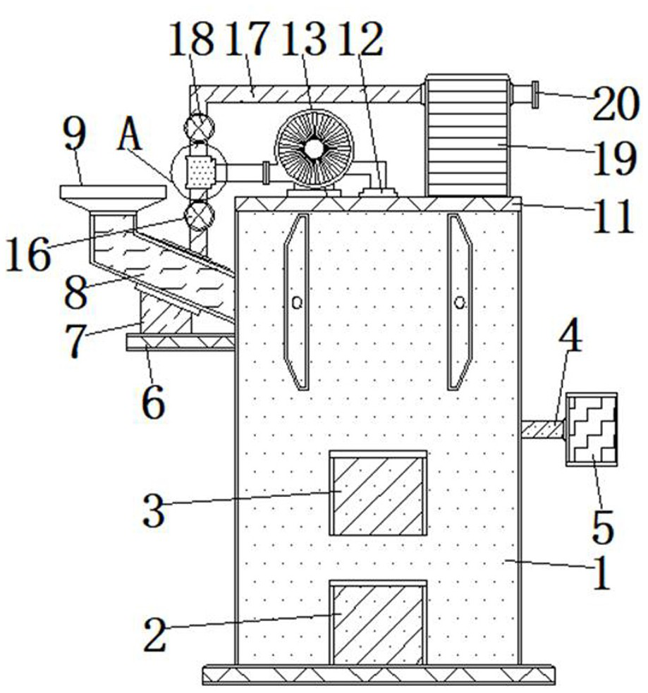
[0023] A waste recycling energy-saving device, comprising a combustion furnace body 1, ash bin door 2 hinged at the bottom end of the front outer wall of the combustion furnace body 1, and a burnout bin door 3 hinged above the front outer wall of the combustion furnace body 1 close to the ash door 2 , the middle part of the outer wall on the right side of the combus...


PUM


Abstract

The invention relates to the technical field of garbage recycling, in particular to garbage recycling energy-saving equipment which comprises a combustion furnace body, an ash bin door is hinged to the bottom end of the outer wall of the front face of the combustion furnace body, and a burnout bin door is hinged to the position, close to the upper portion of the ash bin door, of the outer wall of the front face of the combustion furnace body. A mounting frame is connected to the middle of the outer wall of the right side of the combustion furnace body through bolts, a control box is hinged to the right end of the mounting frame, a supporting plate is welded to the top end of the outer wall of the left side of the combustion furnace body, a carrying frame is connected to the top wall of the supporting plate through bolts, and a discharging channel is welded to the position, close to the upper portion of the supporting plate, of the outer wall of the left side of the combustion furnace body. A discharging hopper is welded to an end opening of the upper left side of the discharging channel, a gas guide cover is installed on the inclined inner wall of the top of the discharging channel in an embedded mode, a top cover is hinged to the top wall of the combustion furnace body, and an exhaust port is fixedly formed in the middle of the top wall of the top cover. And the practicability is high.

Description

technical field [0001] The invention relates to the technical field of garbage recovery, in particular to energy-saving equipment for garbage recovery. Background technique [0002] Garbage is a waste item that loses its use value and cannot be used. It is an important link in the material cycle and is an unnecessary or useless solid or fluid substance. In densely populated big cities, garbage disposal is a headache. The common way is to collect it and send it to landfill for landfill treatment, or to incinerate it in an incinerator, but both will create environmental protection problems , and ending excessive consumption can further reduce the saturation of landfills. Garbage disposal in landfills will not only pollute groundwater and emit bad smells, but also the area available for landfills in many cities has become less and less, and incineration is inevitable. Toxic gas is produced, harmful to organisms, and most cities are researching ways to reduce waste generation a...

Claims


Application Information

Patent Timeline
Patent Type & Authority Applications(China)
IPC IPC(8): F23G5/04F23G5/44F23G5/46F23G5/50F23J15/02A61L9/20
CPCF23G5/04F23G5/444F23G5/46F23G5/50F23J15/025A61L9/20F23J2217/10
Inventor 宁超祥
Owner 张家界三红果业开发有限公司
Why Eureka
Try Eureka