Eureka AIR delivers breakthrough ideas for toughest innovation challenges, trusted by R&D personnel around the world.

Confocal microscopic device capable of accurately measuring transverse and longitudinal acoustic phonon velocities of medium

An acoustic phonon and confocal microscopy technology, applied in measuring devices, measuring ultrasonic/sonic/infrasonic waves, microscopes, etc., can solve angle deviation, increase the complexity of the measurement system and measurement process, and it is difficult to ensure the in-situ of right-angle scattering measurement results and accuracy issues, to achieve the effect of ensuring in-situ, accuracy, and rapid measurement

Pending Publication Date: 2022-04-19
BEIJING INST OF RADIO METROLOGY & MEASUREMENT
View PDF0 Cites 0 Cited by
  • Summary
  • Abstract
  • Description
  • Claims
  • Application Information

AI Technical Summary

Problems solved by technology

However, the existing Brillouin spectroscopy test methods generally use the combination of right-angle scattering and backscattering, which usually needs to rotate the direction of the illumination optical axis or collection optical axis, so that the system is in the backscattering configuration or right-angle scattering configuration. , and then detect the transverse acoustic phonon and longitudinal acoustic phonon velocity, therefore, in the measurement process, it is necessary to repeatedly rotate the optical path angle, which greatly increases the complexity of the measurement system and the measurement process
At the same time, rotating the optical path often brings a certain angle deviation, which makes it difficult to ensure the in-situ and accuracy of the right-angle scattering and backscattering measurement results

Method used


Image

  • Confocal microscopic device capable of accurately measuring transverse and longitudinal acoustic phonon velocities of medium
  • Confocal microscopic device capable of accurately measuring transverse and longitudinal acoustic phonon velocities of medium

Examples


Embodiment Construction

[0018] The present invention to solve the technical problems, technical solutions and beneficial effects are more clearly understood, the following in conjunction with the accompanying drawings and embodiments, the present invention is further elaborated in detail. It should be understood that the specific embodiments described herein are merely used to explain the present invention and are not intended to qualify the present invention.

[0019] It should be noted that when a part is said to be "fixed to" or "set to" another part, it can be directly on another part or indirectly on that other part. When a component is said to be "connected to" another component, it can be directly or indirectly connected to the other component.

[0020] It should be understood that the term "length", "width", "up", "down", "front", "back", "left", "right", "vertical", "horizontal", "top", "bottom" and other indications of the orientation or position relationship is based on the orientation or posi...


PUM


Abstract

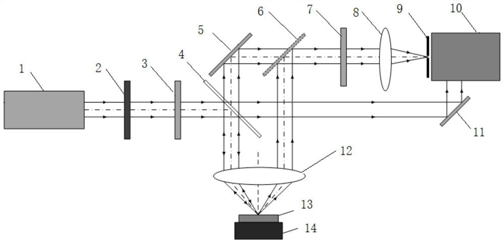
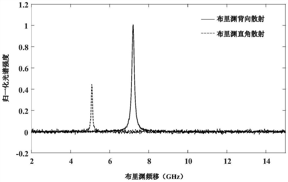
The confocal microscopic device capable of accurately measuring the transverse and longitudinal acoustic phonon velocities of the medium comprises a continuous laser, a three-dimensional translation stage and an F-P interferometer, a to-be-measured sample is placed on the upper side of the three-dimensional translation stage, and a measuring objective lens is arranged right above the to-be-measured sample; a lambda / 2 wave plate, a polarizer, a light splitting plain film and a first reflecting mirror are sequentially arranged on one side of the continuous laser; and a confocal pinhole, a convergent lens, an analyzer, a rotary reflector and a second reflector are sequentially arranged on one side of the F-P interferometer. According to the invention, the angle between the incident light path and the scattered light path does not need to be changed in the measurement process, the acoustic phonon speed of the measured material is rapidly measured by dynamically switching the collected light paths, the in-situ property and accuracy of the measurement result are ensured, and the measurement efficiency is improved. The method has remarkable advantages in the aspects of measuring speed, measuring precision, measuring mode complexity and the like.

Description

Technical field [0001] The present invention belongs to the field of microspectral measurement technology, specifically relates to a confocal microscopy device that can accurately measure the lateral and longitudinal acoustic phonon velocity of the medium. Background [0002] The stiffness tensor of the material can be directly used to calculate a series of mechanical properties parameters such as the elastic modulus, shear modulus, poisson ratio of the material, etc., and the complete acquisition of the stiffness tensor of the material is of great significance for characterizing the mechanical properties of the material. The traditional measurement method is mainly calculated by measuring the stress-strain curve of the material, but this method has great limitations. First of all, contact measurement will lead to deformation of the plastic material, and in the process of measuring it, it is easy to introduce additional measurement errors, resulting in unstable measurement resul...

Claims


Application Information

Patent Timeline
Patent Type & Authority Applications(China)
IPC IPC(8): G01N21/47G01N21/49G01N21/63G01H9/00G02B21/00
CPCG01N21/47G01N21/49G01N21/636G01H9/00G02B21/0024G01N2021/4709G01N2021/4726G01N2021/4735G01N2021/638G01N2021/637G01N2201/0666G01N2201/06113
Inventor 吴寒旭杨宏雷付洋杨文哲吕宇涛
Owner BEIJING INST OF RADIO METROLOGY & MEASUREMENT
Why Eureka
Eureka Blog
Learn More