Hydraulic transmission control system

A technology of hydraulic transmission and control system, which is applied in transmission control, fluid pressure actuation device, fluid transmission device, etc., can solve the problem of locking delay, low reliability and stability, and inability to completely lock the cylinder piston rod. Shrinkage and other problems, to ensure reliable and stable work, reliable and stable disconnection or engagement, and prevent hydraulic oil from flowing backwards

Pending Publication Date: 2022-04-19
贵州凯星液力传动机械有限公司
View PDF7 Cites 0 Cited by
  • Summary
  • Abstract
  • Description
  • Claims
  • Application Information

AI Technical Summary

Problems solved by technology

Although this patent document has multiple hydraulic oil circuits, when the hydraulic components fail, there are other hydraulic oil circuits to ensure the reliable and stable operation of the entire hydraulic control system. However, in the existing hydraulic transmission control systems, a single lock The oil cylinder is connected to the friction clutch, and then drives the switching of the working state of the hydraulic transmission through the friction clutch. Because the existing hydraulic transmission control system is driven by a single lock-up oil cylinder, the reliability and stability are not high. When the friction clutch is in the disconnected state , when the lock-up cylinder is not fully released, the piston rod of the lock-up cylinder cannot be fully retracted back into the body of the lock-up cylinder, which will easily affect the stability of the entire control system. When the lock-up cylinder is required to drive the friction clutch to engage, due to the lock-up The size of the oil inlet port of the oil cylinder is limited, so that the hydraulic oil cannot quickly enter the locking cylinder, so that there is a locking delay phenomenon in the entire hydraulic control system

Method used


Image

  • Hydraulic transmission control system
  • Hydraulic transmission control system
  • Hydraulic transmission control system

Examples


Embodiment Construction

[0020] The technical solution of the present invention is further described below, but the scope of protection is not limited to the description.

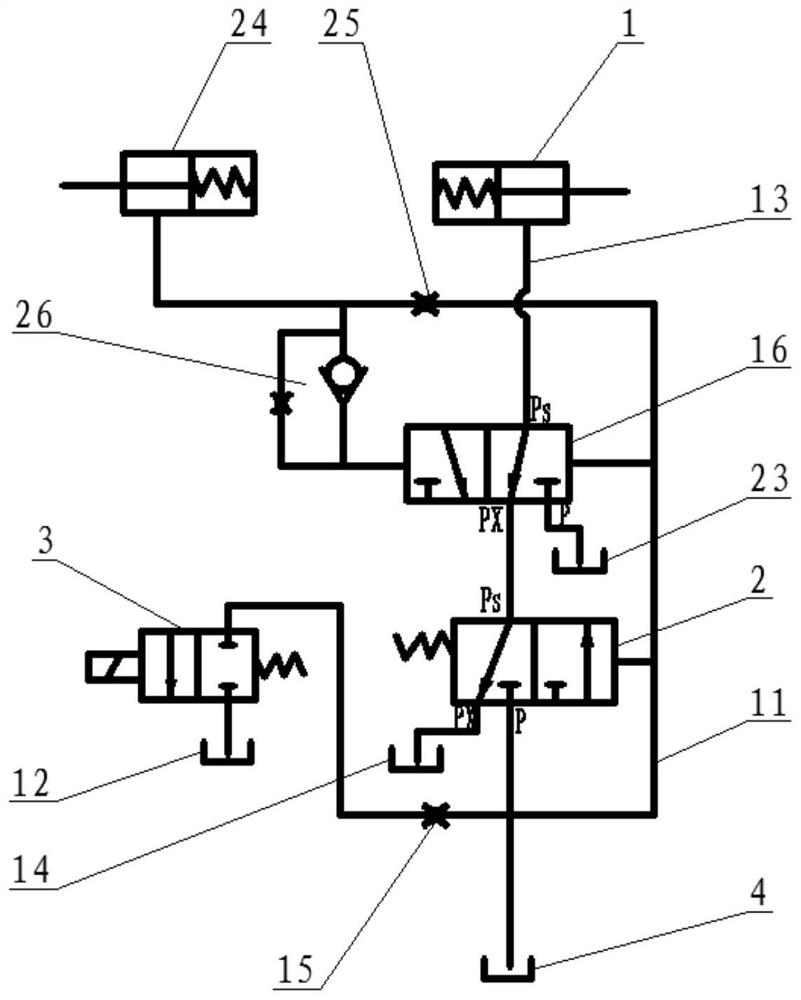
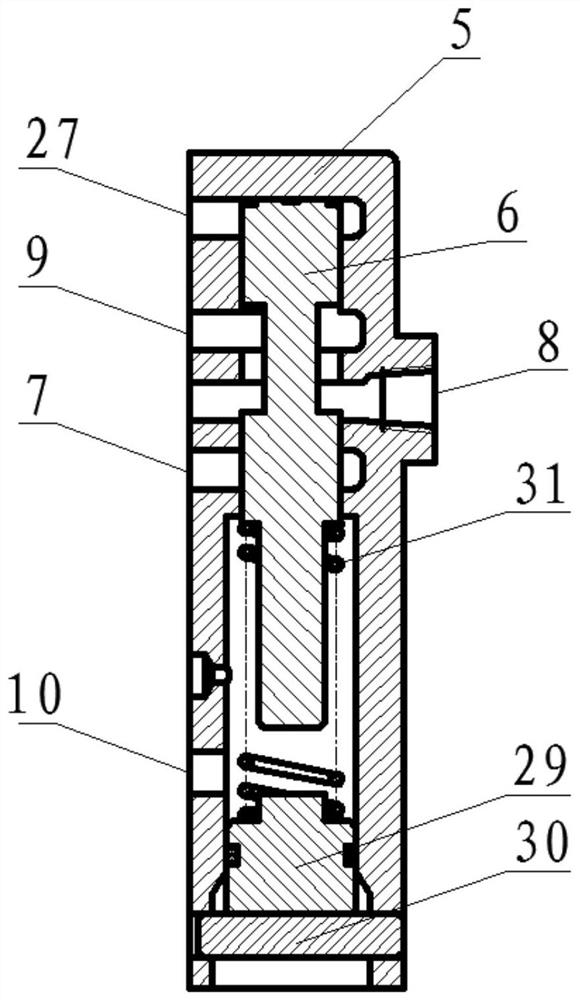
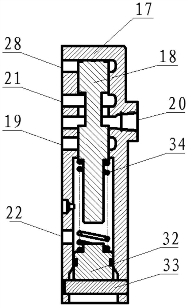
[0021] Such as Figure 1 to Figure 3 As shown, the present invention provides a hydraulic transmission control system, including a lock-up oil cylinder 1, a lock-up valve 2, a solenoid valve 3 and a source oil tank 4, the piston rod of the lock-up oil cylinder 1 is connected with the hydraulic transmission through a friction clutch, and locked Valve 2 includes a valve body A5 and a spool A6. The valve body A5 is provided with an oil inlet Pa7, an oil outlet Psa8, an oil drain Pxa9 and an oil control port Pda10. The oil outlet Psa8 communicates with the oil drain Pxa9 to form an oil drain Channel A, the oil inlet Pa7 communicates with the oil outlet Psa8 to form an oil inlet channel A, the valve core A6 is accommodated in the valve body A5 and through its own reciprocating motion, the oil drain channel A and the oil inlet channel A ...


PUM


Abstract

The invention provides a hydrodynamic transmission control system which comprises a locking oil cylinder, a locking valve, an electromagnetic valve and a source oil tank, a piston rod of the locking oil cylinder is connected with a hydrodynamic transmission through a friction clutch, the locking valve comprises a valve body A and a valve element A, the valve body A is provided with an oil inlet Pa, an oil outlet Psa, an oil drainage port Pxa and an oil control port Pda, the oil outlet Psa and the oil drainage port Pxa are communicated and form an oil drainage channel A, and the oil control port Pda is communicated with the oil control port Pda. The oil inlet Pa is communicated with the oil outlet Psa to form an oil inlet channel A. The valve element A is contained in the valve body A and enables the oil drainage channel A and the oil inlet channel A to be switched and communicated through reciprocating motion, the oil control port Pda is connected into the oil drainage tank A through an oil control pipe and an electromagnetic valve, and the locking oil cylinder is communicated with the oil outlet Psa through an oil guide pipe, and the oil inlet Pa is communicated with the source oil tank through an oil guide pipe. By the adoption of the technical scheme, linkage control is achieved through the locking valve and the unlocking valve, the flow direction of hydraulic oil is controlled through the throttling valve and the one-way valve, pressure of the locking oil cylinder is fully relieved, and disconnection or connection of the friction clutch is more reliable and stable.

Description

technical field [0001] The invention belongs to the technical field of hydraulic transmission control systems, in particular to a hydraulic transmission control system. Background technique [0002] At present, hydraulic control systems have been widely used in various light industries, machine tools, engineering machinery, metallurgical machinery, plastic machinery, agricultural and forestry machinery, automobiles, ships and other fields, and the application fields are still expanding. Today, more than 95% Construction machinery, 90% of CNC machining centers, and more than 95% of automatic production lines all use hydraulic control systems. The existing hydraulic transmission control systems used in vehicles are mainly composed of loads, hydraulic pumps, valve blocks, oil pipes and other components. , the existing hydraulic transmission control system generally uses the oil pressure output by the hydraulic pump to provide power to drive the load to complete the correspondin...

Claims


Application Information

Patent Timeline
Patent Type & Authority Applications(China)
IPC IPC(8): F16H61/40F16H61/14F15B13/01F15B13/02
CPCF16H61/40F16H61/14F15B13/01F15B13/02
Inventor 张芳张正富
Owner 贵州凯星液力传动机械有限公司
Why Eureka
Try Eureka