
Multi-grid radio frequency inductive coupling ion source

A radio frequency inductive coupling and ion source technology, applied in the field of ion beam control, can solve problems such as thermally stable installation of insulator sputtering pollution, affecting the long-term stable operation of the ion source, and increasing the beam spot, so as to ensure long-term stable operation and suppress gas The effect of breakdown discharge and large beam spot

Pending Publication Date: 2022-04-15
SOUTHWESTERN INST OF PHYSICS +1
View PDF23 Cites 0 Cited by
  • Summary
  • Abstract
  • Description
  • Claims
  • Application Information

AI Technical Summary

Problems solved by technology

[0004] As the beam spot increases, the design and processing of extraction gates for large-area and multi-gate ion sources becomes more and more difficult
Deformation control and thermal stability issues, how to prevent the installation of insulators between multiple grids from being polluted by sputtering, and affecting the long-term stable operation of the ion source need to be resolved urgently

Method used


Image

  • Multi-grid radio frequency inductive coupling ion source
  • Multi-grid radio frequency inductive coupling ion source
  • Multi-grid radio frequency inductive coupling ion source

Examples


Embodiment 1

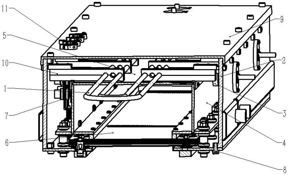
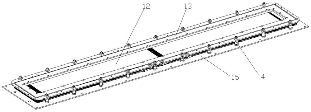
[0034] like figure 1 As shown, a multi-gate RF inductively coupled ion source includes a RF coupling antenna 1, an ion source shielded water-cooled enclosure 2, a voltage isolation gas circuit connector 3, a side wall of a plasma discharge chamber 4, a dielectric coupling window 5, and a plasma discharge chamber. Chamber 6, Elastic lead wire system 7, Rectangular grid lead-out system 8, Mounting back plate 9, Antenna holder 10, Lead snap ring 11, Grid assembly 12, Mounting bottom plate 13, Mounting plate fixing member combination 14, Grid mounting plate 15. Grid assembly one 16. Grid assembly two 17. Grid installation assembly 18.

[0035] The plasma discharge chamber 6 is located below the radio-frequency coupling antenna 1, and is a cubic cavity composed of the dielectric coupling window 5, the discharge chamber side wall 4 and the extraction grid of the rectangular grid extraction system 8. The plasma discharge chamber 6 is provided with The ion source shields the water-co...

Embodiment 2

[0052] like Image 6 As shown, a multi-gate circular RF inductively coupled ion source. The difference between this embodiment and the first embodiment is that it is a circular extraction system, which is suitable for the ion beam treatment process of small substrates.


PUM


Abstract

The invention belongs to the technical field of ion beam control, and particularly relates to a multi-grid radio frequency inductive coupling ion source. A plasma discharge chamber is located below a radio frequency coupling antenna and is a cubic cavity composed of a dielectric coupling window, a discharge chamber side wall and an extraction grid of a rectangular grid extraction system, and an ion source shielding water-cooling shell and an installation back plate are arranged outside the plasma discharge chamber. Symmetrically arranged antenna clamping seats are arranged between the upper part of the plasma discharge chamber and the mounting back plate, and a dielectric coupling window is arranged between the two antenna clamping seats; the radio frequency coupling antenna is installed on the antenna clamping seat, an elastic lead system is arranged between the side wall of the plasma discharge chamber and the ion source shielding water-cooling shell, a rectangular grid leading-out system is arranged at the bottom of the plasma discharge chamber, and a lead clamping ring is installed on the upper portion of the installation back plate. According to the invention, high-uniformity collimated ion beam current can be generated in a large size range, and compared with a two-gate structure and a three-gate structure, the uniformity of the high-uniformity collimated ion beam current is remarkably improved.

Description

technical field [0001] The invention belongs to the technical field of ion beam control, and in particular relates to a multi-grid radio frequency induction coupling ion source. Background technique [0002] The characteristic of RF inductively coupled ion source is that it can produce high density pure plasma. It provides current density and uniformity for pre-cleaning, etching, ion beam assisted deposition (IBAD), and is ideal for optical coatings and thin film deposition, including metal oxides and other dielectric materials. It is one of the most widely used ion sources in the fields of modern thin film material preparation, material surface modification, VLSI and high-precision large-scale optical component microfabrication. [0003] With the continuous increase of ion source extraction cross section required by these application fields, an ion source with large area, high uniformity, and multi-gate ion beam extraction system is required. By increasing the grid, the ma...

Claims


Application Information

Patent Timeline
Patent Type & Authority Applications(China)
IPC IPC(8): H01J37/08H01J37/32
Inventor 陈庆川黄琪聂军伟赵哲石连天孙振华王丁
Owner SOUTHWESTERN INST OF PHYSICS
Learn More